Crank the engine over is the injectors clicking? Better comeback am fixing to go
BTW are you getting spark and correct fuel pressure.[/Quote:291ae8abc4]
The injectors are not clicking.
My son ran the car out of oil. The motor locked up. We had bought a used motor when we bought the car. We changed motors; plugged everything in; etc. The car would not start. Through toubleshooting and with your help, we determined that the injectors are not pulsing. The car will start, but as I stated before, only with carb cleaner or starter fluid, but will not stay started at all. We purchased another used computer; we have plugged, unplugged, and checked every ground wire there is. We have changed the distributor and located the crank sensor. We think that the crank sensor is good, but are not sure. Thank you very much for the help.[/Quote:291ae8abc4]
Do you have a reference voltage on the CPS, try cranking the engine and backprobe the signal wire are you gettin anything.
Checking CPS resistances:
Auto-166-204 ohms @ 77degs F
Manual-423-528 ohms @ " "
Check it and comeback
About the injectors maybe shot -never know. Are you getting fuel all the way to the rail or TBI unit.
Okay why don't you get a noid light and test the injector connectors.
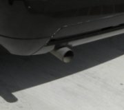
The cam and crank sensors tells the computer the firing order position/the speed and position of the crankhaft-now the computer has to get an ignition signal in order for it to energize the injectors thru the quad driver. Could be when the ECM don't get the ignition signal equals to no injection for the purpose of the unburned fuel collecting in the exhaust to ruin the converter.[/Quote:291ae8abc4]
The CPS resistance, if we are testing it right, is at 531. It is a manual transmission. We are not sure what you are referring to when you say "backprobe the signal wire". We are getting fuel all the way to the rail. We have checked all of the fuel injectors. The power side is fine; but the pulse side nothing. Would it have something to do with the ignition relay? We don't know what the quad driver is. Is it something that we can check? Thanks again for all the help.[/Quote:291ae8abc4]
The quad driver is in the computer
How about the 5volts on the CPS wire do you have it?
At the CPS the black wire should have the 5volts when key is On. White is the signal back to the computer. To confrim it -disconnect the coolant temp. Sensor-check voltage at black wire on it do you have it.
Check injectors resistances should be 10-14ohms.
Now final approach on the wiring:
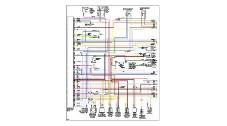
Turn ignition off-disconnect the ECM harness connector. Check continuity between ECM harness connector terminal No.102 Red/Black wire to injector harness wire, No.104 Green/Black wire to injector wire, No.107 yellow/blk, No.109 blue/Blk-
102/104/107/109 are all the pulsing wire going to the injector which is the grounding wire the ECM uses to pulse the Injs.
If no continuity repair or replace harness or connector- Continuity all there-we stop on the Injectors. The injectors okay were right back to ECM terminal/ harness/connectors for damage/corrosion.
Good Luck Gentlemen[/quote:291ae8abc4]
We do not have the 5 volts on the cps wire. There is also no voltage on the black wire on the coolant temp sensor.
We have continuity on the 102/104/107/109 wires.
Thanks again.[/Quote:291ae8abc4]
How about the white wire at CPS and brown/yellow at CTS?
At pin 50 check for continuity on the black to the black wire at CPS[/quote:291ae8abc4]
There is no voltage on the white wire at CPS; we are not sure what the CTS is; we do have continuity at pin 50 to the black wire.[/Quote:291ae8abc4] If the CTS is the Cam Timing Sensor, there is no brown/yellow wires; there is a six wire plug and a two wire plug going to the distributor.[/Quote:291ae8abc4]
Are you turning On the key when checking the black wire
CTS=Coolant temperature sensor has a black and the brown/yellow
The black wire also goes to TPS throttle position/Crank pos. /IAT=intake air temperature sensor/EGR temp. Sensor. Check cont. On all this sensors to pin out 50
Turn key On look for power at pin 50, do you have it?[/Quote:291ae8abc4]
We tested the CPS on DC Volts with key on nothing - white or black; tested the brown/yellow on CTS have 5 volts; tested pin 50 for continuity with test light - the light came on; tested pin 50 with volt meter on DC volts got nothing. The black wires going to TPS throttle/IAT/EGR/Crank Sensors have no continuity to pin 50.
SPONSORED LINKS
Was this helpful?
Yes
No
Tuesday, August 28th, 2007 AT 8:11 PM