Need to know the pin out on the PCM cable to the IMSC actuator

Tiny
MOOREPAUL
  • MEMBER
  • 2002 FORD RANGER
  • 2.3L
  • 4 CYL
  • 2WD
  • 110,000 MILES
The IMSC actuator is mechanically working but a bench test to give an output to the PCM signaling high or low is not happening from the actuator itself. There are five volts from the PCM connector on either side of the 3 pin cable to the PCM. I can only assume that one of the pins on either side activates pull down signal to the PCM as the center pin in negative. I do not want to hurt the PCM by grounding anything to the PCM by not knowing the exact signal required and it appears that the IMSC actuator does not respond with a switching signal on either outside pin using a five volt power supply on the bench. An internal magnet on the top shaft of the actuator is supposed to effect the device located at the top of the IMSC actuator. Do not know how to proceed at the moment either condemning the actuator or the PCM.
Tuesday, December 5th, 2017 AT 5:54 AM

8 Replies

Tiny
KEN L
  • MASTER CERTIFIED MECHANIC
  • 43,379 POSTS
It does sounds like the wiring is having a problem. Here is a guide and the engine wiring diagrams (below) to help you confirm the failure and get the truck fixed.

https://www.2carpros.com/articles/how-to-check-wiring

Check out the diagrams (below).

Let us know what happens and please upload pictures or videos of the problem.

Cheers, Ken
Was this
answer
helpful?
Yes
No
+1
Thursday, December 7th, 2017 AT 10:54 AM
Tiny
STEVE W.
  • MECHANIC
  • 13,071 POSTS
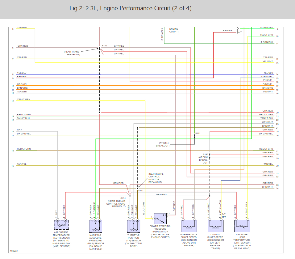
It is a three wire potentiometer circuit.

Pin 2 grey/red wire is sensor return to the PCM on pin 91 and shares that with the MAP, TPS and most of the other sensors.

Pin 1 white wire is the sensor signal feed to the PCM at Pin 8.

Pin 3 brown/white wire is the five volt reference signal from the PCM at pin 90 and shares that with the MAP, TPS, and the fuel tank pressure sensor.
Was this
answer
helpful?
Yes
No
Thursday, December 7th, 2017 AT 11:31 AM
Tiny
MOOREPAUL
  • MEMBER
  • 4 POSTS
When the cold weather abates I will look into it as I am helping a good friend with it. My earlier ohms check read zero on the center pin of the cable towards the PCM to negative ground using my Fluke high impedance meter. I actually managed to get inside the IMSC actuator as I have ways of looking into things that others wouldn't dare to touch and put it back together with epoxy and maintained the vacuum diaphragm integrity throughout the device. The 3 pins are integrated into a sealed button on the top cap of the IMSC. There is a small magnet on the top of the actuator shaft which comes near when the actuator retracts and closes the butterflies with vacuum and activates the 3 pin button for an output. So, it has to get pretty darn close to do anything to effect a signal to the PCM as it is a small magnet. As I indicated before I could not manage any form of variable signal on the bench from the actuator. With 3 pins it does not appear to be rocket science as I have a degree in electronics from decades ago and now retired. I have constructed hall effect devices in circuits before so I suspected it was either some form of hall effect device or otherwise and internal sealed mechanical switch or as you indicated might be a potentiometer. In either case I cannot effect any output change. I guess I will have to play with it a little more.
Was this
answer
helpful?
Yes
No
Thursday, December 7th, 2017 AT 2:25 PM
Tiny
KEN L
  • MASTER CERTIFIED MECHANIC
  • 43,379 POSTS
Can you send images of the IMSC actuator I always wanted to see inside. It sounds like the actuator is not responding.
Was this
answer
helpful?
Yes
No
Friday, December 8th, 2017 AT 4:41 PM
Tiny
MOOREPAUL
  • MEMBER
  • 4 POSTS
Sure thing Ken. The left shows the sealed round button inside the cap which is attached to the 3 pins on the opposite side not shown. The right shows the small round magnet attached to the moveable shaft which when coming close to the cap button on butterfly closure then activates the 3 pin button device on the left. The spring pushes the butterflies open and magnet away from the electronic button with absence of vacuum. Taking it apart and putting it back together and making it work again with vacuum to activate the shaft is tricky, but fortunately with my extensive mechanical and machine background along with electrical experience I can sometimes go where others have not gone before. Sometimes you win and sometimes you don't. Grateful for a win this time. Problem now is locating a replacement without purchasing a whole new manifold.
Was this
answer
helpful?
Yes
No
Saturday, December 9th, 2017 AT 6:37 AM
Tiny
KEN L
  • MASTER CERTIFIED MECHANIC
  • 43,379 POSTS
That is so interesting, you are a pioneer going where other fear to tread :) Please let me know what happens.

Best, Ken
Was this
answer
helpful?
Yes
No
Saturday, December 9th, 2017 AT 10:25 AM
Tiny
MOOREPAUL
  • MEMBER
  • 4 POSTS
We shall see what happens next. Thanks for you help with the wiring on the pin out !
Was this
answer
helpful?
Yes
No
Sunday, December 10th, 2017 AT 4:20 AM
Tiny
KEN L
  • MASTER CERTIFIED MECHANIC
  • 43,379 POSTS
:)
Was this
answer
helpful?
Yes
No
Saturday, December 16th, 2017 AT 1:01 PM

Please login or register to post a reply.

Sponsored links