INTAKE MANIFOLD
Removal
Remove negative battery cable. Remove dynamic chamber cover by removing nuts in center of cover, then unsnapping clips along side of cover from front to back. Release fuel pressure. See FUEL PRESSURE RELEASE . Drain cooling system. Remove charge air cooler air duct. Remove air cleaner assembly with air ducts.
Remove MAF sensor and air intake hose. Remove air resonator box. Remove left and right charge air coolers. Remove accelerator cable. Remove air intake pipes that connected to charge air cooler assemblies. Remove EGR valve.
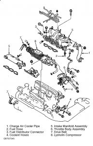
Remove charge air cooler pipe and fuel inlet hose. See Fig. 5 . Remove fuel distributor connector. Remove coolant hose at throttle body and intake manifold. Remove intake manifold assembly.
Installation
To install reverse removal procedure. Install all intake manifold retaining bolts and nuts before tightening to specification. Tighten all fasteners in sequence to specification. See Fig. 6 .
Install and tighten all retaining bolts to specification. See TORQUE SPECIFICATIONS . When installing charge air cooler air intake pipe assembly, hand tighten listed nuts and bolts until air intake pipe No. 3 meets intake manifold. See Fig. 7 . Ensure rubber collars are not twisted or distorted. Tighten bolts in sequence. Tighten bolts "A" to 70-95 INCH lbs. (7.9-10.7 N.m). Tighten all other bolts shown to 14-18 ft. lbs. (19-25 N.m).
Hand tighten listed nuts and bolts until charge air coolers and air intake pipe No. 1 and No. 2 meet intake manifold. See Fig. 8 . Ensure rubber collars are not twisted or distorted. Tighten bolts "A" to 44-78 INCH lbs. (5.0-8.8 N.m). Tighten bolts "B" to 70-95 INCH lbs. (7.9-10.7 N.m). Tighten all other bolts shown to 14-18 ft. lbs. (19-25 N.m).
To install remaining components, reverse removal procedure. Fill and bleed cooling system. See COOLING SYSTEM BLEEDING . Ensure accelerator cable has .04-.08" (1.0-3.0 mm) free play at throttle body when installed. If free play is not as specified, rotate nut on end of cable at throttle body until specified free play is obtained.
Fig. 5: Exploded View Of Intake Manifold & Related Componen
SPONSORED LINKS
Wednesday, March 17th, 2010 AT 10:56 AM