Okay, you need to test the actual fuel pressure.
Roy
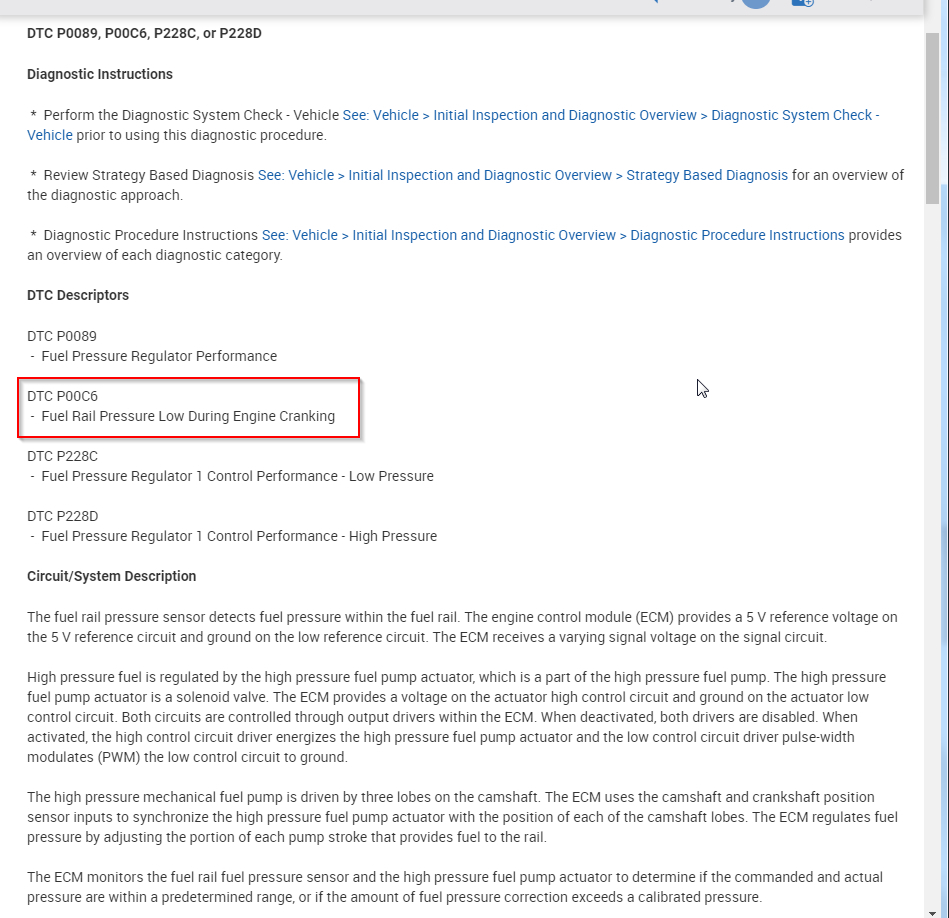
DTC P0089, P00C6, P228C, or P228D
Diagnostic Instructions
Perform the Diagnostic System Check - Vehicle See: Vehicle > Initial Inspection and Diagnostic Overview > Diagnostic System Check - Vehicle prior to using this diagnostic procedure.
Review Strategy Based Diagnosis See: Vehicle > Initial Inspection and Diagnostic Overview > Strategy Based Diagnosis for an overview of the diagnostic approach.
Diagnostic Procedure Instructions See: Vehicle > Initial Inspection and Diagnostic Overview > Diagnostic Procedure Instructions provides an overview of each diagnostic category.
DTC Descriptors
DTC P0089
Fuel Pressure Regulator Performance
DTC P00C6
Fuel Rail Pressure Low During Engine Cranking
DTC P228C
Fuel Pressure Regulator 1 Control Performance - Low Pressure
DTC P228D
Fuel Pressure Regulator 1 Control Performance - High Pressure
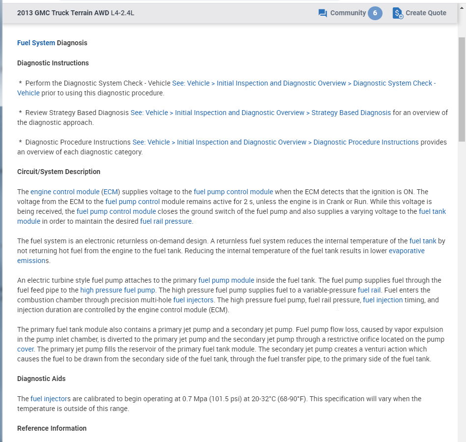
Circuit/System Description
The fuel rail pressure sensor detects fuel pressure within the fuel rail. The engine control module (ECM) provides a 5 V reference voltage on the 5 V reference circuit and ground on the low reference circuit. The ECM receives a varying signal voltage on the signal circuit.
High pressure fuel is regulated by the high pressure fuel pump actuator, which is a part of the high pressure fuel pump. The high pressure fuel pump actuator is a solenoid valve. The ECM provides a voltage on the actuator high control circuit and ground on the actuator low control circuit. Both circuits are controlled through output drivers within the ECM. When deactivated, both drivers are disabled. When activated, the high control circuit driver energizes the high pressure fuel pump actuator and the low control circuit driver pulse-width modulates (PWM) the low control circuit to ground.
The high pressure mechanical fuel pump is driven by three lobes on the camshaft. The ECM uses the camshaft and crankshaft position sensor inputs to synchronize the high pressure fuel pump actuator with the position of each of the camshaft lobes. The ECM regulates fuel pressure by adjusting the portion of each pump stroke that provides fuel to the rail.
The ECM monitors the fuel rail fuel pressure sensor and the high pressure fuel pump actuator to determine if the commanded and actual pressure are within a predetermined range, or if the amount of fuel pressure correction exceeds a calibrated pressure.
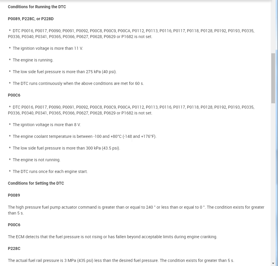
Conditions for Running the DTC
P0089, P228C, or P228D
DTC P0016, P0017, P0090, P0091, P0092, P00C8, P00C9, P00CA, P0112, P0113, P0116, P0117, P0118, P0128, P0192, P0193, P0335, P0336, P0340, P0341, P0365, P0366, P0627, P0628, P0629 or P1682 is not set.
The ignition voltage is more than 11 V.
The engine is running.
The low side fuel pressure is more than 275 kPa (40 psi).
The DTC runs continuously when the above conditions are met for 60 s.
P00C6
DTC P0016, P0017, P0090, P0091, P0092, P00C8, P00C9, P00CA, P0112, P0113, P0116, P0117, P0118, P0128, P0192, P0193, P0335, P0336, P0340, P0341, P0365, P0366, P0627, P0628, P0629 or P1682 is not set.
The ignition voltage is more than 8 V.
The engine coolant temperature is between -100 and +80°C (-148 and +176°F).
The low side fuel pressure is more than 300 kPa (43.5 psi).
The engine is not running.
The DTC runs once for each engine start.
Conditions for Setting the DTC
P0089
The high pressure fuel pump actuator command is greater than or equal to 240 ° or less than or equal to 0 °. The condition exists for greater than 5 s.
P00C6
The ECM detects that the fuel pressure is not rising or has fallen beyond acceptable limits during engine cranking.
P228C
The actual fuel rail pressure is 3 MPa (435 psi) less than the desired fuel pressure. The condition exists for greater than 5 s.
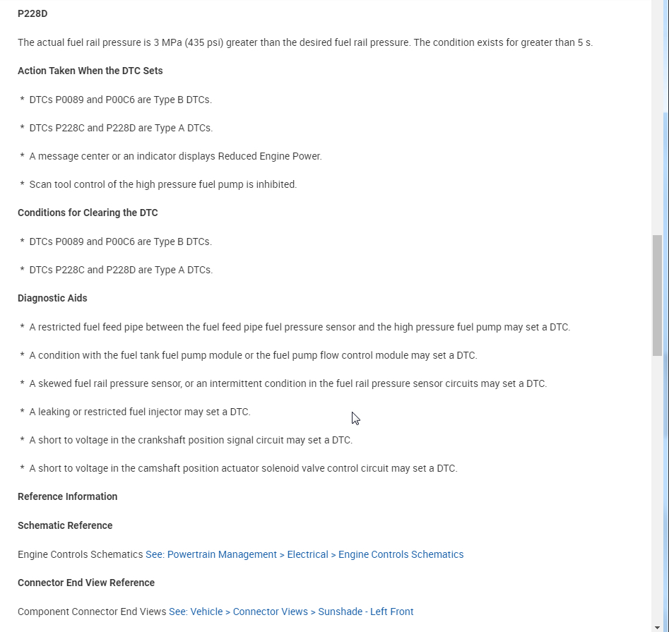
P228D
The actual fuel rail pressure is 3 MPa (435 psi) greater than the desired fuel rail pressure. The condition exists for greater than 5 s.
Action Taken When the DTC Sets
DTCs P0089 and P00C6 are Type B DTCs.
DTCs P228C and P228D are Type A DTCs.
A message center or an indicator displays Reduced Engine Power.
Scan tool control of the high pressure fuel pump is inhibited.
Conditions for Clearing the DTC
DTCs P0089 and P00C6 are Type B DTCs.
DTCs P228C and P228D are Type A DTCs.
Diagnostic Aids
A restricted fuel feed pipe between the fuel feed pipe fuel pressure sensor and the high pressure fuel pump may set a DTC.
A condition with the fuel tank fuel pump module or the fuel pump flow control module may set a DTC.
A skewed fuel rail pressure sensor, or an intermittent condition in the fuel rail pressure sensor circuits may set a DTC.
A leaking or restricted fuel injector may set a DTC.
A short to voltage in the crankshaft position signal circuit may set a DTC.
A short to voltage in the camshaft position actuator solenoid valve control circuit may set a DTC.
Reference Information
Schematic Reference
Engine Controls Schematics See: Powertrain Management > Electrical > Engine Controls Schematics
Connector End View Reference
Component Connector End Views See: Vehicle > Connector Views > Sunshade - Left Front
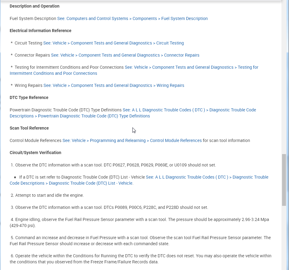
Description and Operation
Fuel System Description See: Computers and Control Systems > Components > Fuel System Description
Electrical Information Reference
Circuit Testing See: Vehicle > Component Tests and General Diagnostics > Circuit Testing
Connector Repairs See: Vehicle > Component Tests and General Diagnostics > Connector Repairs
Testing for Intermittent Conditions and Poor Connections See: Vehicle > Component Tests and General Diagnostics > Testing for Intermittent Conditions and Poor Connections
Wiring Repairs See: Vehicle > Component Tests and General Diagnostics > Wiring Repairs
DTC Type Reference
Powertrain Diagnostic Trouble Code (DTC) Type Definitions See: A L L Diagnostic Trouble Codes ( DTC ) > Diagnostic Trouble Code Descriptions > Powertrain Diagnostic Trouble Code (DTC) Type Definitions
Scan Tool Reference
Control Module References See: Vehicle > Programming and Relearning > Control Module References for scan tool information
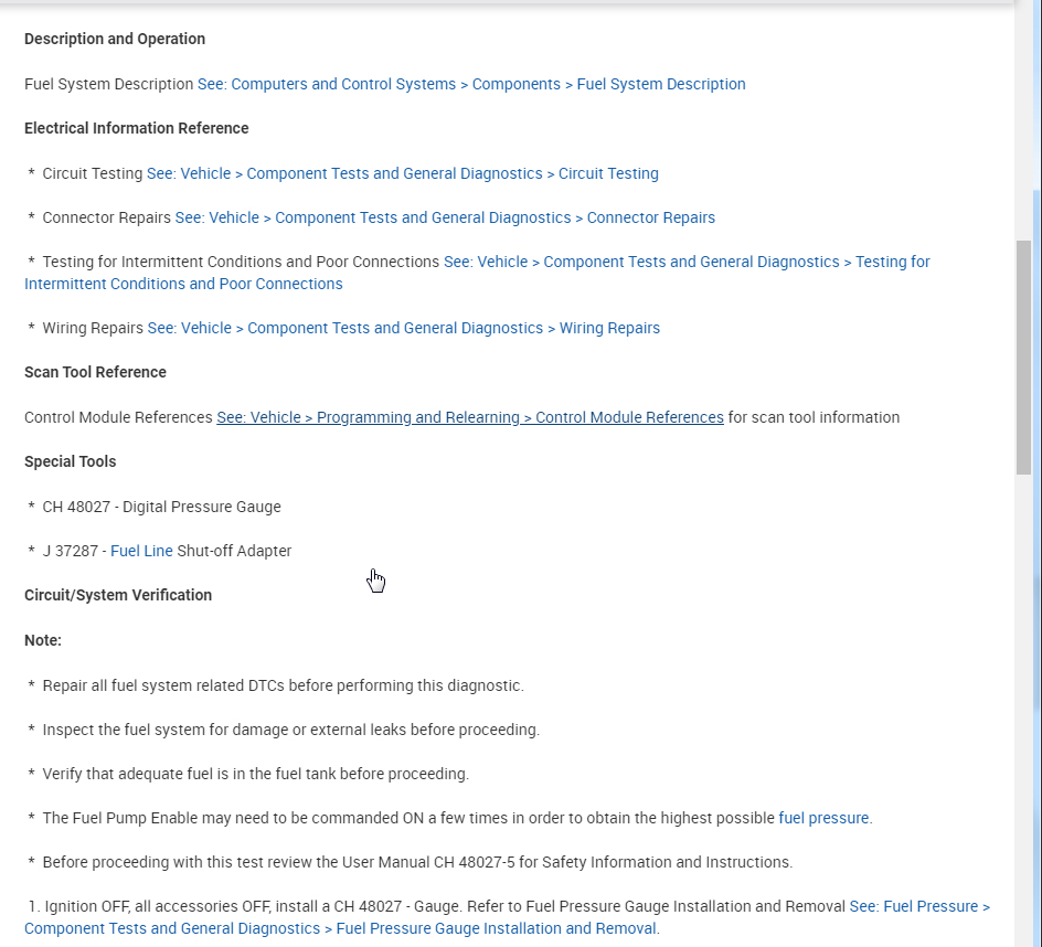
Circuit/System Verification
1. Observe the DTC information with a scan tool. DTC P0627, P0628, P0629, P069E, or U0109 should not set.
If a DTC is set refer to Diagnostic Trouble Code (DTC) List - Vehicle See: A L L Diagnostic Trouble Codes ( DTC ) > Diagnostic Trouble Code Descriptions > Diagnostic Trouble Code (DTC) List - Vehicle.
2. Attempt to start and idle the engine.
3. Observe the DTC information with a scan tool. DTCs P0089, P00C6, P228C, and P228D should not set.
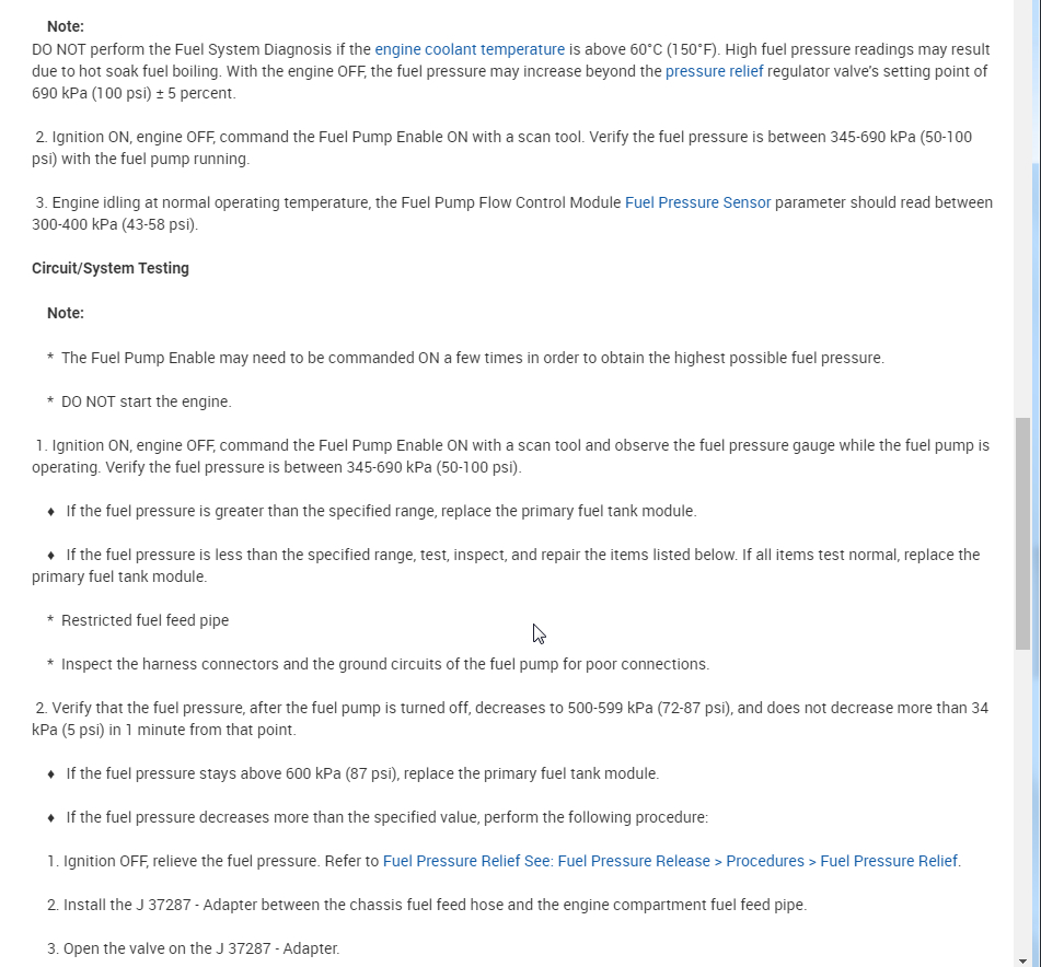
4. Engine idling, observe the Fuel Rail Pressure Sensor parameter with a scan tool. The pressure should be approximately 2.96-3.24 Mpa (429-470 psi).
5. Command an increase and decrease in Fuel Pressure with a scan tool. Observe the scan tool Fuel Rail Pressure Sensor parameter. The Fuel Rail Pressure Sensor should increase or decrease with each commanded state.
6. Operate the vehicle within the Conditions for Running the DTC to verify the DTC does not reset. You may also operate the vehicle within the conditions that you observed from the Freeze Frame/Failure Records data.
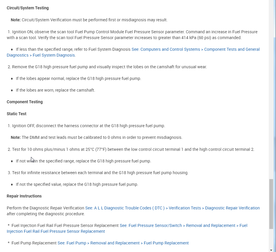
Circuit/System Testing
Note: Circuit/System Verification must be performed first or misdiagnosis may result.
1. Ignition ON, observe the scan tool Fuel Pump Control Module Fuel Pressure Sensor parameter. Command an increase in Fuel Pressure with a scan tool. Verify the scan tool Fuel Pressure Sensor parameter increases to greater than 414 kPa (60 psi) as commanded.
If less than the specified range, refer to Fuel System Diagnosis See: Computers and Control Systems > Component Tests and General Diagnostics > Fuel System Diagnosis.
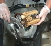
2. Remove the G18 high pressure fuel pump and visually inspect the lobes on the camshaft for unusual wear.
If the lobes appear normal, replace the G18 high pressure fuel pump.
If the lobes are worn, replace the camshaft.
Component Testing
Static Test
1. Ignition OFF, disconnect the harness connector at the G18 high pressure fuel pump.
Note: The DMM and test leads must be calibrated to 0 ohms in order to prevent misdiagnosis.
2. Test for 10 ohms plus/minus 1 ohms at 25°C (77°F) between the low control circuit terminal 1 and the high control circuit terminal 2.
If not within the specified range, replace the G18 high pressure fuel pump.
3. Test for infinite resistance between each terminal and the G18 high pressure fuel pump housing.
If not the specified value, replace the G18 high pressure fuel pump.
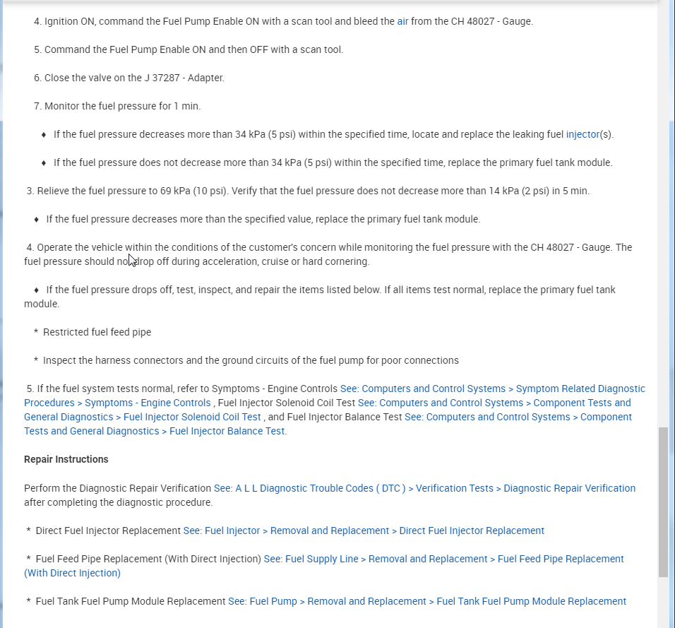
Repair Instructions
Perform the Diagnostic Repair Verification See: A L L Diagnostic Trouble Codes ( DTC ) > Verification Tests > Diagnostic Repair Verification after completing the diagnostic procedure.
Fuel Injection Fuel Rail Fuel Pressure Sensor Replacement See: Fuel Pressure Sensor/Switch > Removal and Replacement > Fuel Injection Fuel Rail Fuel Pressure Sensor Replacement
Fuel Pump Replacement See: Fuel Pump > Removal and Replacement > Fuel Pump Replacement
Intake Camshaft and Valve Lifter Replacement See: Camshaft, Engine > Removal and Replacement > Intake Camshaft and Valve Lifter Replacement
Tuesday, April 7th, 2020 AT 7:58 AM