Welcome back:
Here are the directions for replacement. The first 26 pictures correlate with the removal process. This is an extensive process. You will need to prop the engine in place to remove a motor mount.
______________________________
Timing Belt Removal
Vehicle Engine, Cooling and Exhaust Engine Timing Components Timing Belt Service and Repair Procedures Timing Belt Replace Timing Belt Removal
TIMING BELT REMOVAL
REMOVAL
1. DISCONNECT NEGATIVE TERMINAL CABLE FROM BATTERY
CAUTION (w/SRS): Work must be started more than 90 seconds after the time the ignition switch is turned to the "LOCK" position and the negative (-) terminal cable is disconnected from the battery.
2. REMOVE RH ENGINE UNDER COVER
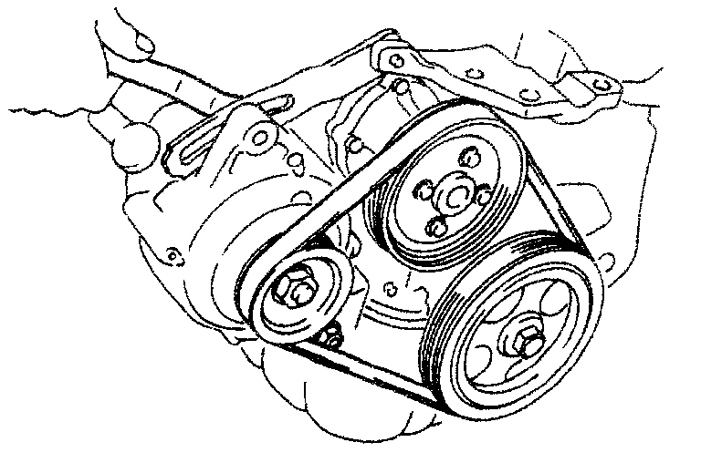
3. WITH A/C OR PS: REMOVE DRIVE BELT
A. Remove PS pump drive belt
Loosen the 2 bolts, and remove the drive belt.
B. Remove A/C compressor drive belt. Loosen the idler mounting nut and adjusting bolts, and remove the drive belt.
4. REMOVE GENERATOR DRIVE BELT
Loosen the pivot nut and adjusting bolt, and remove the drive belt.
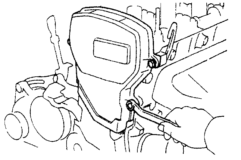
5. WITH CRUISE CONTROL SYSTEM: REMOVE CRUISE CONTROL ACTUATOR
(a)Remove the actuator cover.
(b)Disconnect the actuator connector.
(c)Remove the 3 bolts and actuator.
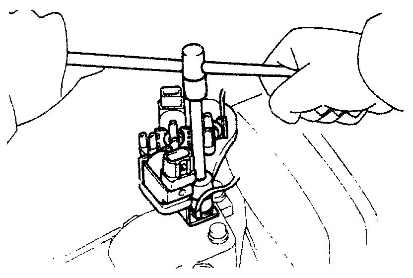
6. REMOVE VSV ASSEMBLY
(a)Disconnect the VSV connector(s).
(b)Disconnect the vacuum hoses.
(c)Remove the bolt, ground strap and VSV assembly.
7. SLIGHTLY JACK UP ENGINE
Raise the engine enough to remove the weight from the engine mounting on the right side.
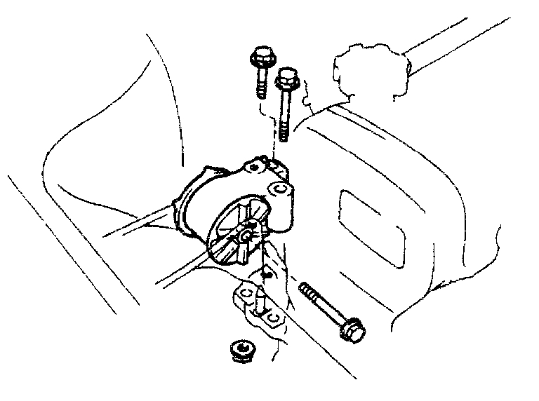
8. REMOVE RH ENGINE MOUNTING INSULATOR
Remove the through bolt, 2 bolts, nuts and mounting insulator.
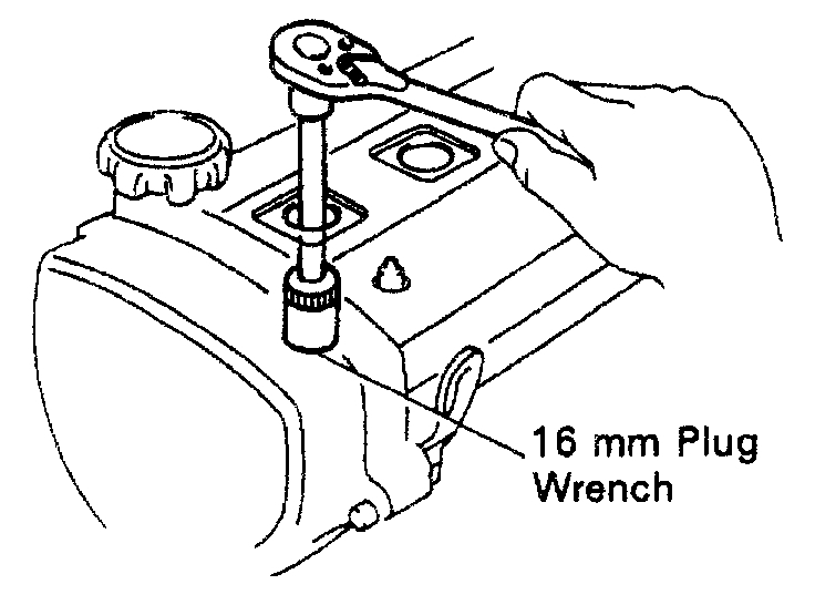
9. REMOVE SPARK PLUGS
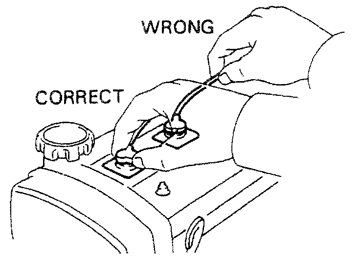
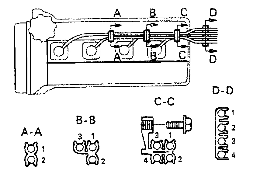
(a)Disconnect the high-tension cords at the rubber boot.
Do not pull on the cords.
NOTICE: Pulling on or bending the cords may damage the conductor inside.
(b)Using a 16 mm plug wrench, remove the 4 spark plugs.
10. REMOVE CYLINDER HEAD COVER
(a)Remove the oil filler cover.
(b)Remove the 5 cap nuts and seal washers.
(c)Pry out the cylinder head cover, and remove the cover and gasket.
11. REMOVE NO.2 TIMING BELT COVER
Remove the 4 bolts, timing belt cover and gasket.
12. SET NO.1 CYLINDER TO TDC/COMPRESSION
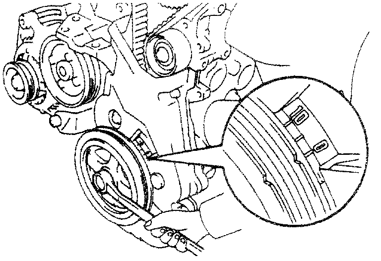
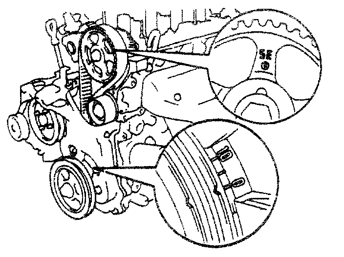
(a)Turn the crankshaft pulley, and align its groove with the timing mark "0" of the No.1 timing belt cover.
NOTICE: Always turn the crankshaft clockwise.
(b)Check that the hole of the camshaft timing pulley is aligned with the timing mark of the bearing cap. If not, turn the crankshaft pulley 1 complete revolution (360°).
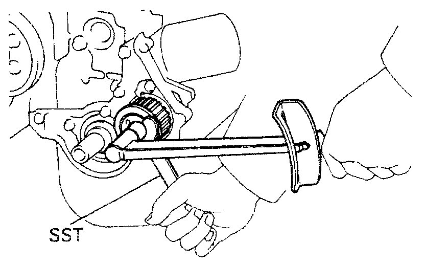
13. REMOVE CRANKSHAFT PULLEYS
(a)WITH A/C OR PS: Remove the 4 bolts and No.2 crankshaft pulley.
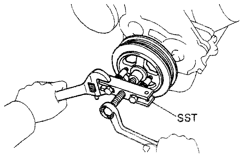
(b)Install SST to the crankshaft pulley.
SST 09213-14010
(c)Using SST to hold the crankshaft pulley, loosen the pulley bolt.
SST 09330-00021
(d)Remove the SST and pulley bolt.
(e)Using SST, remove the pulley.
SST 09213-31021
14. REMOVE NO.3 TIMING BELT COVER
15. REMOVE NO.1 TIMING BELT COVER
Remove the 3 bolts, timing belt cover and gasket.
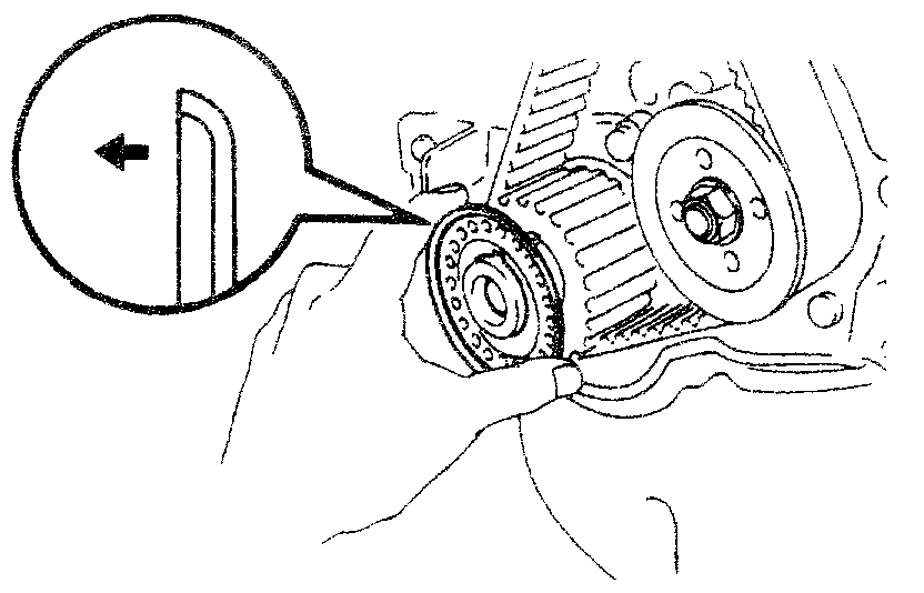
16. REMOVE TIMING BELT GUIDE
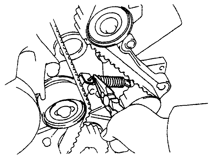
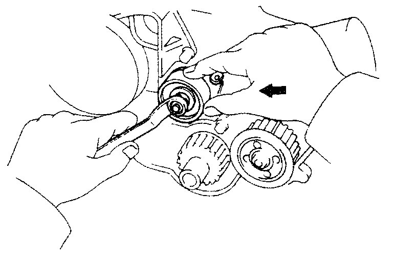
17. REMOVE TIMING BELT AND NO.1 IDLER PULLEY
HINT: If reusing the timing belt, draw a direction arrow on the belt (in direction of engine revolution), and place matchmarks on the pulleys and belt as shown in the illustration.
(a)Remove the tension spring.
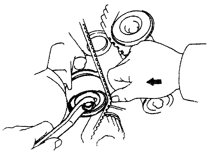
(b)Loosen the idler pulley bolt and push it left as far as it will go and then temporarily tighten it.
(c)Remove the timing belt.
(d)Remove the idler pulley bolt and pulley.
18. REMOVE No.2 IDLER PULLEY
Remove the bolt and pulley.
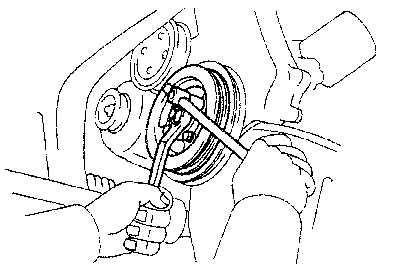
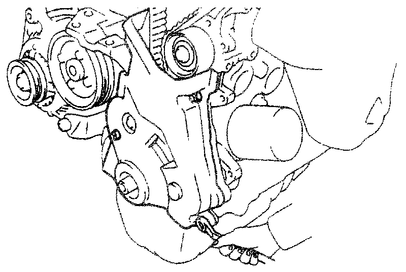
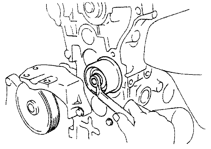
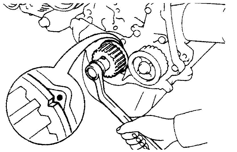
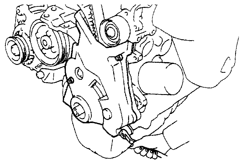
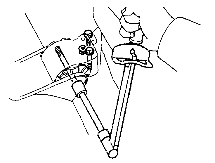
19. REMOVE CRANKSHAFT TIMING PULLEY
If the timing pulley cannot be removed by hand, use 2 screwdrivers.
NOTICE: Position shop rags as shown to prevent damage.
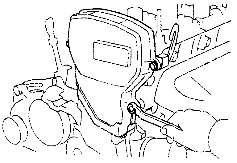
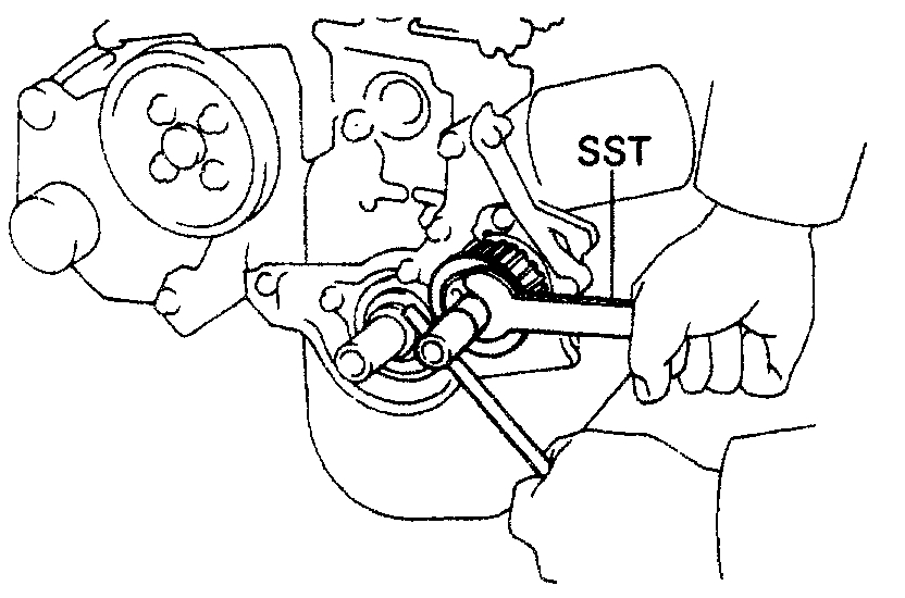
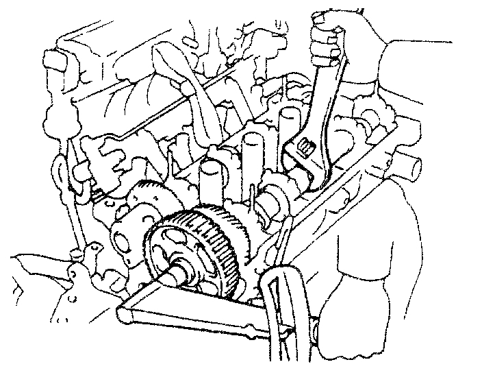
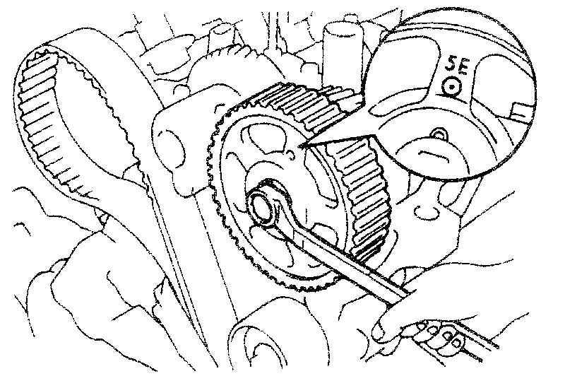
20. REMOVE CAMSHAFT TIMING PULLEY
Hold the camshaft with the wrench, and remove the pulley set bolt and timing pulley.
NOTICE: Be careful not to damage the cylinder head with the wrench.
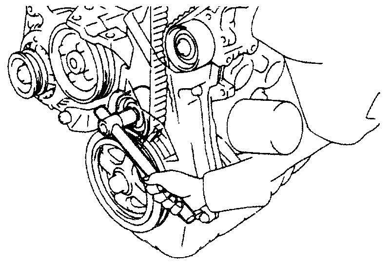
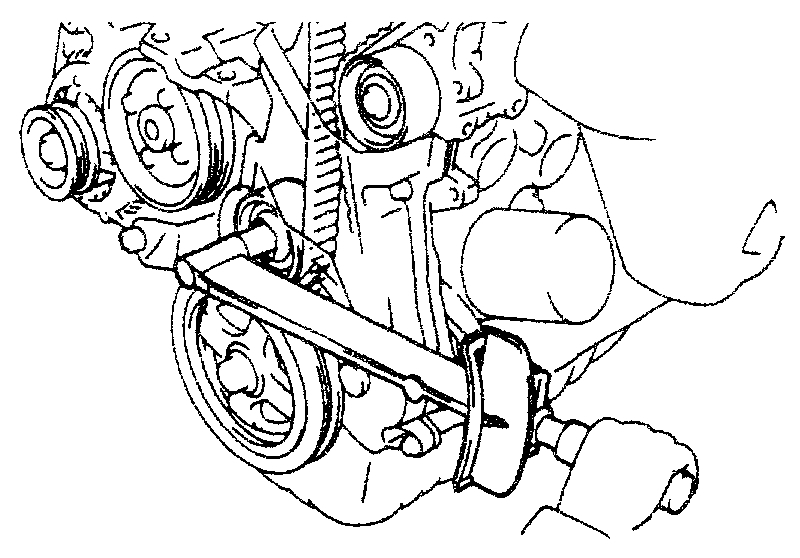
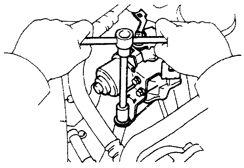
21. REMOVE OIL PUMP PULLEY
Using SST to hold the pulley, remove the pulley nut and pulley.
SST 09616-12011
___________________________________
Here are the directions for replacement. The remaining pictures correlate with replacement.
__________________________________
Timing Belt Installation
Vehicle Engine, Cooling and Exhaust Engine Timing Components Timing Belt Service and Repair Procedures Timing Belt Replace Timing Belt Installation
TIMING BELT INSTALLATION
INSTALLATION
1. INSTALL OIL PUMP PULLEY
(a)Align the pulley and oil pump drive shaft.
(b)Using SST to hold the pulley. Torque the nut.
SST 09616-12011
Torque: 36 N.M (370 kgf. Cm. 27 ft. Lbf)
2. INSTALL CAMSHAFT TIMING PULLEY
(a)Align the camshaft knock pin with the knock pin groove of the pulley slide on the pulley.
(b)Temporary install the timing pulley bolt.
(c)Hold the hexagonal wrench head portion of the cam shaft with a wrench. And tighten the timing pulley bolt.
Torque: 50 N.M (510 kgf. Cm, 37 ft. Lbf)
3. INSTALL CRANKSHAFT TIMING PULLEY
(a)Align the pulley set key with the key groove of the pulley.
(b)Slide on the timing pulley, facing the flange side inward.
(c)Using the crankshaft pulley bolt, turn the crankshaft and align the timing marks of the crankshaft timing pulley and oil pump body.
4. INSTALL NO.2 IDLER PULLEY
Install the pulley with the bolt.
Torque: 27 N.M (280 kgf. Cm. 20 ft. Lbf)
HINT: Remove any oil or water on the idler pulley and keep it clean.
5. TEMPORARILY INSTALL NO.1 IDLER PULLEY AND TENSION SPRING
(a)Install the pulley with the bolt. Do not tighten the bolt yet.
(b)Pry the pulley toward the left as far as it will go and temporarily tighten the bolt.
HINT: Remove any oil or water on the idler pulley and keep it clean.
6. TEMPORARILY INSTALL TIMING BELT
NOTICE: The engine should be cold.
Install the timing belt on the crankshaft timing, oil pump, No.1 idler and No.2 idler pulleys.
HINT: If reusing timing belt, align the points marked during removal and install the belt with the arrow pointing in the direction of engine revolution.
7. INSTALL TIMING BELT GUIDE
Install the guide, facing the cup side outward.
8. INSTALL NO.1 TIMING BELT COVER
(a)Install the gasket to the belt cover.
(b)Install the belt cover with the 3 bolts.
9. INSTALL CRANKSHAFT PULLEY
(a)Align the pulley set key with the key groove of the pulley.
(b)Install the pulley bolt and SST to the crankshaft pulley.
SST 09213-14010
(c)Using SST to hold the crankshaft pulley, torque the pulley bolt.
SST 09330-00021
Torque: 152 N.M (1,550 kgf. Cm, 112 ft. Lbf)
(d)With A/C and/or PS: Install the No.2 crankshaft pulley with the 4 bolts.
Torque: 19 N.M (195 kgf. Cm, 14 ft. Lbf)
10. SET NO.1 CYLINDER TO TDC/COMPRESSION
(a)Turn the crankshaft pulley. And align its groove with timing mark "0" of the No.1 timing belt cover.
(b)Turn the camshaft, and align the hole of the camshaft timing pulley with the timing mark of the bearing cap.
11. INSTALL TIMING BELT
HINT: If reusing the timing belt, first align the matchmarks of the belt and camshaft timing pulley.
Install the timing belt, ensure that there is tension between the crankshaft timing pulley, oil pump pulley and camshaft timing pulley.
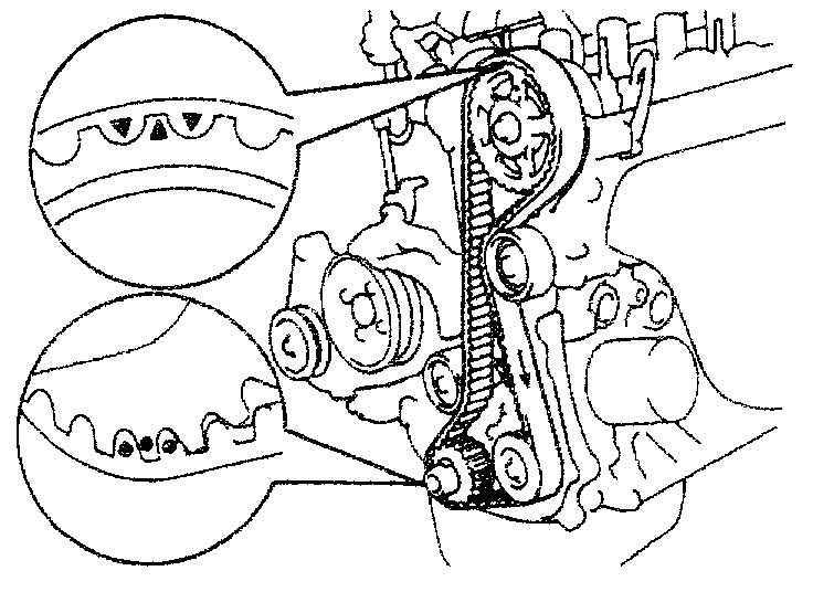
12. CHECK VALVE TIMING
(a)Loosen the No.1 idler pulley mount bolt, until the pulley is moved slightly by the spring tension.
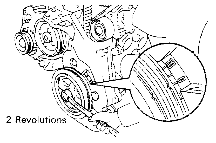
(b)Turn the crankshaft pulley 2 revolutions from TDC to TDC.
NOTICE: Always turn the crankshaft clockwise.
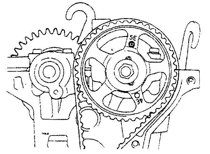
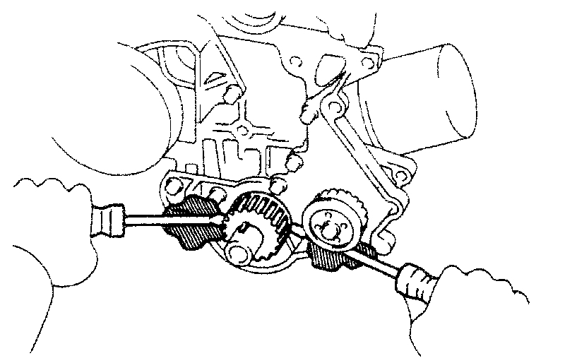
(c)Check that each pulley aligns with the timing marks as shown in the illustration.
If the timing marks do not align, remove the timing belt and reinstall it.
(d)Torque the mounting bolt of the No.1 idler pulley.
Torque: 18 N.M (185 kgf. Cm, 13 ft. Lbf)
13. INSTALL NO.3 TIMING BELT COVER
14. INSTALL NO.2 TIMING BELT COVER
(a)Install the gasket to the belt cover.
(b)Install the belt cover with the 4 bolts.
15. INSTALL CYLINDER HEAD COVER
(a)Apply seal packing to the cylinder head as shown in the illustration.
Seal packing: Part No.08826-00080 or equivalent
(b)Install the gasket to the cylinder head cover.
(c)Install the cylinder head cover with the 5 seal washers and cap nuts.
Torque: 6.9 N.M (70 kgf. Cm, 61 in. Lbf)
(d)Install the oil filler cap.
16. INSTALL SPARK PLUGS
(a)Using a 16 mm plug wrench, install the 4 spark plugs.
Torque: 18 N.M (180 kgf. Cm, 13 ft. Lbf)
(b)Connect the high-tension cords as shown.
(c)Install the cord support bolt to the cylinder head cover.
17. INSTALL RH ENGINE MOUNTING INSULATOR
(a)Attach the RH mounting insulator to the mounting bracket and body, and temporarily install the through bolt, 2 bolts and nut.
(b)Torque the 2 bolts, nut and through bolt of the RH mounting insulator.
Torque:
73 N.M (740 kgf. Cm, 54 ft. Lbf) for Through bolt
64 N.M (650 kgf. Cm, 47 ft. Lbf) for Others
18. INSTALL VSV ASSEMBLY
(a)Install the VSV assembly and ground strap with the bolt.
(b)Connect the vacuum hoses as shown.
(c)Connect the VSV connector(s).
19. With Cruise Control System: INSTALL CRUISE CONTROL ACTUATOR
(a)Install the actuator with the 3 bolts.
(b)Connect the actuator connector.
(c)Install the actuator cover.
20. INSTALL GENERATOR DRIVE BELT
Temporarily install the drive belt with the pivot nut and adjusting bolt.
21. With A/C and/or PS: INSTALL DRIVE BELT
22. ADJUST DRIVE BELTS
A. Adjust generator drive belt
(a)Loosen the pivot nut and adjusting bolt.
(b)Tighten the adjusting bolt. Pushing down the generator from lower side of the vehicle with the generator bracket as fulcrum.
Torque: 12 N.M (120 kgf. Cm. 9 ft. Lbf)
(c)Tighten the pivot nut and through bolt.
Torque: 41 N.M (420 kgf. Cm, 30 ft. Lbf)
(d)Check the belt tension.
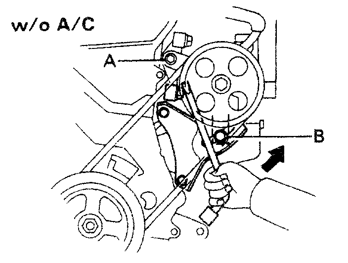
B. Without A/C: Adjust PS pump drive belt
(a)Loosen the bolts A and B.
(b)Tighten the bolt B. Pushing up the PS pump with the pump bracket lower end as fulcrum.
Torque: 39 N.M (400 kgf. Cm. 29 ft. Lbf)
(c)Tighten the bolt A.
Torque: 43 N.M (440 kgf. Cm, 32 ft. Lbf)
(d)Check the belt tension.
C. With A/C: Adjust PS pump drive belt
(a)Loosen the bolts A and B.
(b)Loosen the lock nuts D and E.
(c)Adjust the adjusting bolt F so that its protrusion above nut C is + 0 mm (0 in.).
(d)Fix nut C using lock nut D.
(e)Turn the adjusting bolt F to push up the pump and adjust the belt tension to the specified value.
(f)Tighten the bolts A and B.
Torque:
43 N.M (440 kgf. Cm, 32 ft. Lbf) for Bolt A
39 N.M (400 kgf. Cm, 29 ft. Lbf) for Bolt B
(g)Loosen the adjusting bolt F by 4 or 5 turns.
NOTICE: Check that there is a gap of 5 mm (0.20 in.) Or more between the tip of the nut C and the PS pump body.
(h)Fix the adjusting bolt F with the lock nut E.
(i)Check the belt tension.
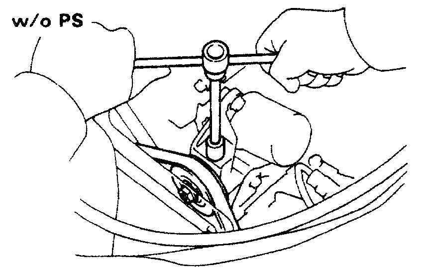
D. Without P/S: Adjust A/C compressor drive belt
(a)Loosen the idler mounting nut.
(b)Turn the adjusting bolt and belt tension to the specified value.
(c)Tighten the idler mounting nut.
23. INSTALL RH ENGINE UNDER COVER
24. CONNECT NEGATIVE TERMINAL CABLE TO BATTERY
_________________________
As you can see, this is quite extensive. Let me know if I can help.
Joe
Images (Click to make bigger)
Saturday, December 22nd, 2018 AT 5:59 PM