I shorted out alternator wire

Tiny
JAY BIRMINGHAM
  • MEMBER
  • 1972 JEEP CJ5
  • 3.8L
  • 6 CYL
  • 4WD
  • MANUAL
  • 142,000 MILES
Cannot get vehicle to turn over by key. Replaced burnt yellow wire from solenoid to alternator with heavier gauge.

I can get starter to jump buy connecting battery cable to starter cable.

I have tested every wire from key wire connector to solenoid for continuity.

I cannot get the key to turnover the starter. I have added a new ballast. I have added a new coil (external resistor), I have added a new solenoid. I have bench tested the solenoid.

I have removed and bypassed the alternator and the coli from the solenoid. Still no bump.

When the alt wire melted down, I pulled the entire "Y" harness, inspected, repaired one small cut and re-wrapped. I never tested continuity on ach wire when off the vehicle. Appeared the only major affect was the alternator wire from solenoid to alternator. I will pull the harness today and test as mush as I can.

Can I continue to test and troubleshoot without ignition and alternator and voltage regulator connected. Should I take the alternator and the 50 you Motorola volt regulator for a test at NAPA. If I melted down the alt wire from the solenoid by a accidental live connection, should I assume I probably fried the alternator and the volt regulator too?

Replace them, put everything back to stock and try again. Also bought a new correct ignition/key and have that in place. I have all photos from before and after.
Sunday, March 24th, 2019 AT 8:45 AM

25 Replies

Tiny
JAY BIRMINGHAM
  • MEMBER
  • 18 POSTS
I removed the y harness and tested every wire cor continuity within the harness, end points to end points.
Was this
answer
helpful?
Yes
No
Sunday, March 24th, 2019 AT 4:31 PM
Tiny
CJ MEDEVAC
  • MECHANIC
  • 11,004 POSTS
The alternator should have no affect to starting system.

Pic 1) This is the way I wired my '46 Willys to be like my CJ 5. The wires on the big posts can be swapped, the starter is always by itself and the battery cable and those wires stay together. "S" and "I" cannot be swapped.

Test

Remove "S" wire from the solenoid. Touch a wire from the Positive side of the battery to "S".

Yep,

If it works, you probably wet your pants, the initial bump will startle you!

It should crank, verifying the solenoid is good.

Before you buy another one, verify the solenoid body is grounded well to it's home spot.

Now let's test "S" wire. Removed from the solenoid, stick your voltmeter probe in the wires socket. Your other lead will go to the negative side of the battery (as there's no better ground than at the source!). Now have your buddy turn the ignition switch to "start". We should get 12 Volts!

No? Let me know!

While we are at it, Turn your key to "on". Stick your probe onto the positive side of your coil.

What do you get?

Okay, lastly until you return with answers.

I took two halves of a diagram and made it into one (courtesy of Prodemand) I colored the wires for "starting" and the "charging" systems. I will eventually color the whole diagram, which makes tracing stuff really easy.

You may find your issue by studying the diagram.

Alright hurry up!

The Jeep needs to be back on the road!

Your turn!

The Medic
Was this
answer
helpful?
Yes
No
+2
Sunday, March 24th, 2019 AT 7:34 PM
Tiny
CARADIODOC
  • MECHANIC
  • 33,749 POSTS
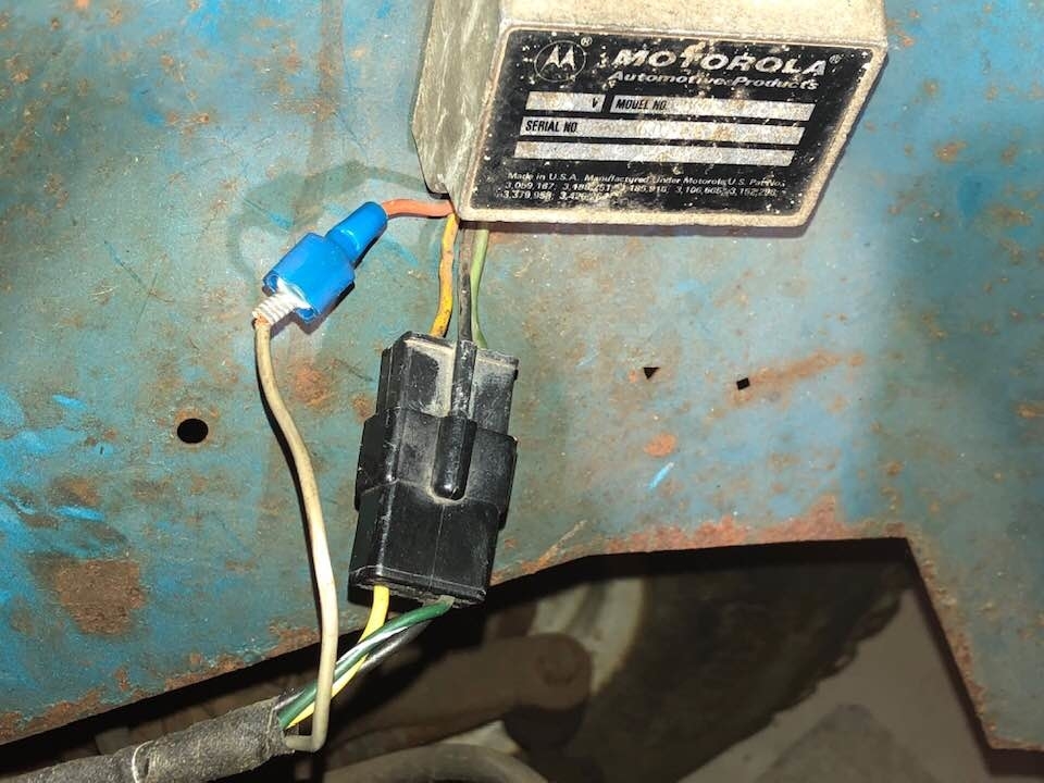
Hold on. You're going about this the wrong way. First let me make a few comments. You can't "fry" the generator unless you connect the case / ground and the output terminal reversed. That will short the internal diodes, but there is always a fuse link wire in that output circuit to protect for that. Second, I'm not sure which wire you replaced, but going to a larger wire is never the answer. The engineers sized the wires to handle every possibility. If you replaced that output wire going back to the battery, you eliminated the fuse link wire, and you removed that circuit's protection. If the right two diodes were to short, you'd have a direct short to ground, a melted output wire, and likely a major car fire. You can be sure an insurance investigator will see the missing fuse link wire and any other modifications.

A fuse link wire is smaller in diameter than the circuit it protects, so it is the weak link in the chain. Its insulation is designed to not melt or burn. You can identify a fuse link wire by its dull color. The color denotes its current rating. You can buy replacement fuse link wire at any auto parts store, but you'll usually get about 12" of wire. That's enough to be cut to make three or four repairs.

Third, removing a generator and carrying it in to an auto parts store is never the right way to test them. A common 50 - 70-amp generator can take over five horsepower to run at maximum output. The bench-testers in stores have, at most, a one horsepower motor. All those can do is tell you if the generator is supplying some current, or nothing. Professional testing involves a lot more than that. All generators need three things to generate current. That is a wire, (a coil of wire), a magnet, (we use an electromagnet), and most importantly, movement between them. That's why the electromagnet has to be spun by the belt. All generators become very inefficient at low speeds. That's why all professional testers require engine speed to be increased to 2,000 rpm during the charging system tests. Bench testers can't increase speed high enough for accurate testing.

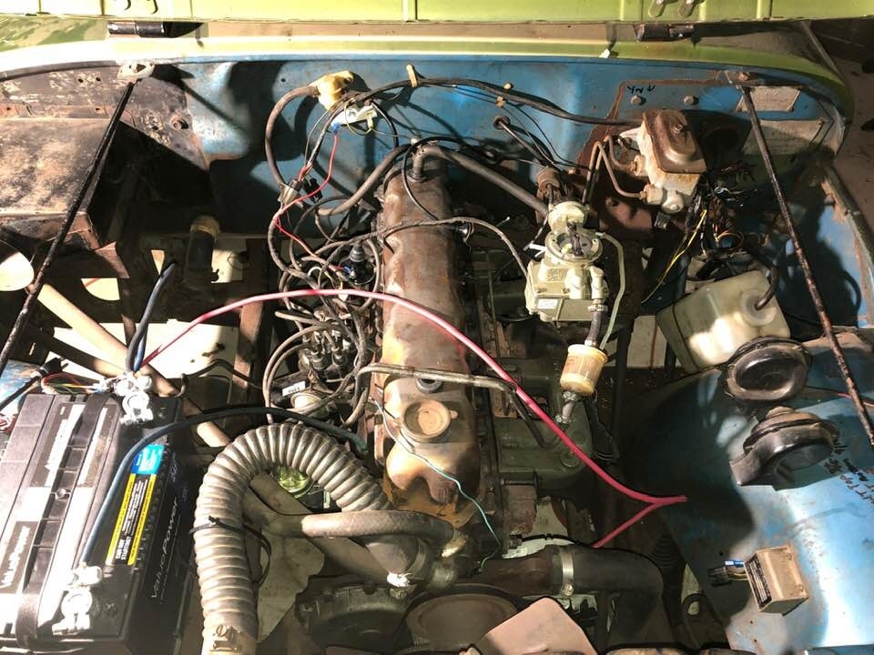
Okay, to get started, you have to understand you're changing parts in three unrelated systems, and you're inserting potentially more problems. Forget the ignition system. You don't need that if the starter system won't crank the engine. Same with the charging system. The only thing to be aware of is AMC and GM commonly used to use the larger starter terminal or the generator's output terminal as convenient tie points instead of running multiple wires back to the battery. Multiple circuits can share a terminal, but that doesn't mean they work together. What can happen is when two or three wires are connected together, it is not uncommon to overlook one and forget to connect it. This happens a lot with GM starters.

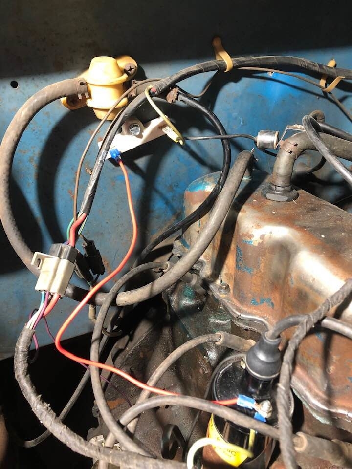
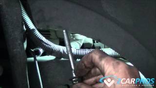
I have one more tidbit of great value. AMC used the Ford-style starter solenoid that sits up on the inner fender near the battery. There are multiple versions of those, and they all look the same. All use the two large terminals, one goes to the battery positive post, and the other goes down to the starter. That is the only wire on the starter.

There's one or two small threaded terminals on top of the solenoid. One gets 12 volts switched onto it when the ignition switch is in the "crank" position. Here's where the differences come in. That switched 12 volts feeds the electromagnetic coil inside, but there has to be a ground connection on the other end of it. In some versions, that is the second small threaded terminal. That one goes to the neutral safety switch, then to ground.

In a different version, that ground terminal is internal to the solenoid's mounting bracket. That means it won't engage if it isn't bolted solidly to the body. This is where some solenoids only have that one small terminal. When there's a second small threaded terminal it is used to bypass the ignition resistor during cranking. When the solenoid engages and switches the very high starter current onto the second large terminal, it also switches 12 volts onto that second small terminal.

The ignition coil has a ballast resistor in series with it to limit current through it to a safe value. During cranking, battery voltage is drawn down, often to less than 10 volts. After the ballast resistor, instead of finding around 9 - 10 volts at the ignition coil, during cranking you'd find closer to 4 - 6 volts. That makes for a very weak spark and hard starting. This is where the 12 volts from the starter solenoid gets switched onto the ignition coil directly. That raises the voltage to get the spark voltage back up to where it should be. In this system, that second wire does not have to be connected for the starter to work. Remember, you'll have weak spark during cranking, but we can work on that later.

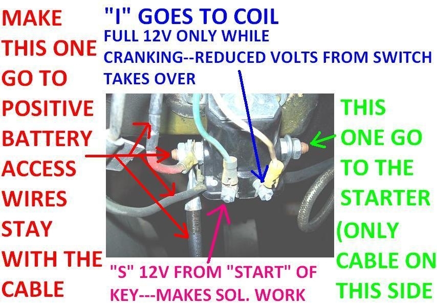
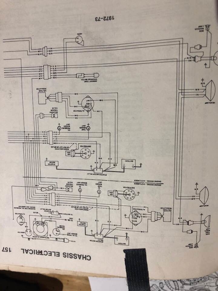
I searched for a couple of hours, but I can't find a wiring diagram that reproduces well enough to be of use. The best I could come up with is this one. The red arrow is pointing to the terminal that connects to the positive battery cable. There's often a second wire attached that feeds all the other circuits including the ignition switch, so that has to be connected for the starting system to work. The blue arrow shows where the cable goes down to the starter. There will never be a second wire hooked there.

On Ford products, the plug-in "S" terminal is a red / blue wire. I've seen that drawn on the right terminal but I don't know if that was a mistake. On every one of these I've ever seen, the red / blue goes on the left, and some solenoids will have the "S" molded in to identify it as the "solenoid" terminal.

The "I" terminal on the right is for "ignition", meaning the ballast resistor bypass. That doesn't have to be connected for the starter system to work in this system. Don't forget, on some versions that is going to the neutral safety switch. In that case it must be connected for the starter to work.

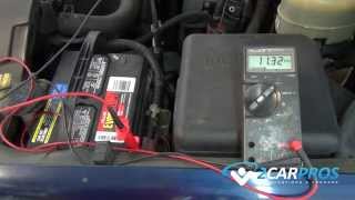
If you don't accomplish anything else for now, use a test light to check for 12 volts on the red / blue wire when you turn the ignition switch to "crank". I doubt you'll need it, but here's a link to an article on using a test light:

https://www.2carpros.com/articles/how-to-use-a-test-light-circuit-tester

You can do this with a digital voltmeter too, but for this type of problem, those can potentially provide incorrect or misleading results. Current has to be able to get through for the solenoid to work, and it must be able to get through for a test light to work.

I'm going to look for a better wiring diagram at home, and if necessary, we can get CJ Medevac involved. He's a "Heep" expert.
Was this
answer
helpful?
Yes
No
+1
Sunday, March 24th, 2019 AT 7:43 PM
Tiny
CARADIODOC
  • MECHANIC
  • 33,749 POSTS
Hi CJ. Sorry I posted before checking if you showed up.

I have two more things to point out. In your first paragraph you said the cables on the two large studs can be switched. If that is done intentionally, don't forget to also move any additional wires that are on the stud that goes to the battery's positive post.

I forgot to mention that when checking to see if you have the right version of solenoid, if the second small terminal is for the neutral safety switch, there will be continuity between those two small terminals, but those can not be switched. The coil itself would work okay, but there is a diode across it to short out the voltage spikes that develop whenever current flow through a coil is stopped. If that spike is allowed to occur, it can go back to the ignition switch and into the other circuits connected to it. More importantly, for that diode to do its job, it's in the circuit backward, so it acts like an open circuit. It becomes "forward-biased" and acts like a short when the voltage spike occurs. If the "S" and "I" wires are switched, the diode will be "forward-biased" when the ignition switch is turned to "crank". It will appear as a short that bypasses the solenoid's coil, so the solenoid won't engage, and the high current is likely to blow a fuse.

I took about a half dozen of these apart to build "bugs" for my students to diagnose, and the other thing I learned is when you jump 12 volts to the "S" terminal to see if the solenoid works, don't leave that jumper on any longer than necessary. After about a minute the coil will overheat and warp, leading to a sticking contact disc. After about two minutes, smoke starts rolling out, then it's all over but the sniveling.
Was this
answer
helpful?
Yes
No
Sunday, March 24th, 2019 AT 8:13 PM
Tiny
JAY BIRMINGHAM
  • MEMBER
  • 18 POSTS
Response to CJ Medevac.
1) "Remove "S:wire from the solenoid, tough a." Answer> No, it did not crank, no spark I then took a heavy from positive battery to starter connection post and it did crank, tried two to three times and cranked.

2) Battery showed low on a cheap battery tester, showed 10.70 on HF Centec and showed 12 on SunPro set at High and Volts.

3) "Now lets test the "S" wire. Removed from Solenoid." Answer Yes, I got 12 volts. This was a big success.

4) 'While Your at it Turn key to On, test positive side of coil" Answer Zero (0). Tested coil volts w ballast connected and disconnected. Zero (0). Note that I may not ( probably did not) re-attache the blue S wire back tot he solenoid. Do I need to do that to test the coil?

Coil is a new Accel 8140C. The old coil I removed was a 12 volt and said "Use with external resistor" May still be good. I keep all parts removed from CJ5 and date and store them.

Thanks,

Jay
Was this
answer
helpful?
Yes
No
Monday, March 25th, 2019 AT 7:18 PM
Tiny
CJ MEDEVAC
  • MECHANIC
  • 11,004 POSTS
Sounds like Mr. Solenoid is either bad, poor connections, or not grounded well.

Mr. Battery needs to be 12 volts- 12 1/2 volts, charge it if needed.

Blue "S" wire only activates the solenoid which makes it crank.

It should have no bearing on the other stuff.

Yea! "S" has 12 Volts! One thing less to troubleshoot!

Send a picture of your solenoid

Heck, left, right, and overhead of your engine with the breather off.

We'll get there, I'll stick with you.

The Medic
Was this
answer
helpful?
Yes
No
Monday, March 25th, 2019 AT 7:43 PM
Tiny
JAY BIRMINGHAM
  • MEMBER
  • 18 POSTS
New solenoid. I also scuffed the fender well with a file to help it ground to the new chrome solenoid bracket. Will REM and scuff them both tonight and clean with some elec term cleaner. May try to ground it out on the negative battery post too, unmounted. I was able to bench test it and did get the solenoid to switch last week. I can also bench test the old solenoid and put that back online. Sunny skies tonight in Delaware!
Was this
answer
helpful?
Yes
No
Tuesday, March 26th, 2019 AT 2:30 AM
Tiny
JAY BIRMINGHAM
  • MEMBER
  • 18 POSTS
Great night and the First State.
1)Reconnected blue wire to Solenoid S. Turned key to ignition, No bump.
2) Reconnected Volt. Regulator and two wires to alt. Alternator main power was already connected. Turned Key to Ignition - Got one Bump at starter!
Was this
answer
helpful?
Yes
No
-1
Tuesday, March 26th, 2019 AT 7:17 PM
Tiny
JAY BIRMINGHAM
  • MEMBER
  • 18 POSTS
Is there a character limit? Did you receive my lines numbered 3, 4, 5 in the above response?
Was this
answer
helpful?
Yes
No
+1
Tuesday, March 26th, 2019 AT 7:27 PM
Tiny
JAY BIRMINGHAM
  • MEMBER
  • 18 POSTS
3)Grounded base of Solenoid to negative battert, Turned key to IGN, no bump.
4)Reconnected SunPro, Volts>High>4 Stroke, Get 3 volt with no key in, get 12 volts at "On":
Was this
answer
helpful?
Yes
No
Tuesday, March 26th, 2019 AT 7:29 PM
Tiny
CJ MEDEVAC
  • MECHANIC
  • 11,004 POSTS
No limits, things glitch every now and then at 2car!

I've written answer/novels for hours, hit submit/ reply and lose every bit of it! For a while there I got smart, I would copy my answer, then re-paste it when it got lost.

One bump? Stopped at that? That was all?

You were turning it to "start" not "ign"?

Explain this, is this the voltmeter we're talking about? SunPro, Volts>High>4 Stroke

Tell me what's on the solenoid. I see the starter, I see the battery.

What's the other big cable?

Where is "I" going to?

The Medic
Was this
answer
helpful?
Yes
No
Tuesday, March 26th, 2019 AT 7:48 PM
Tiny
JAY BIRMINGHAM
  • MEMBER
  • 18 POSTS
Th other two things on the battery cable post n Sol. Are the large red that I made to replace the burnt yellow that went to the alternator. Original cause for all this. The other red is a main the goes into the circuit, looks like up to the firewall connector, over and may terminate at the ignition. I have tested it from the back of the ignition to the solenoid for continuity.
Was this
answer
helpful?
Yes
No
Wednesday, March 27th, 2019 AT 2:07 AM
Tiny
JAY BIRMINGHAM
  • MEMBER
  • 18 POSTS
Yes, all tests were turn to try and start the car. Yes, only one bump. That one time. I have an old SunPro Volt/Ohm/Dwell meter that I have kept in a good case and taken care of. I set it on Volt test, make sure it is set on High (vs Low for low volt batteries) and 4 stroke vs. 2 stroke setting. I will send a picture. These two pictures are from 1972 Jeep Shop Manual.
Was this
answer
helpful?
Yes
No
Wednesday, March 27th, 2019 AT 2:16 AM
Tiny
JAY BIRMINGHAM
  • MEMBER
  • 18 POSTS
These two images are from Chilton. I also have the Haynes. And will send PICS tonight. Thank you for your service. Note also, when I just use batter POS cable to Starter Cable, by hand, mid air, not connected to anything else.I can crank it over all day. Do I son't think it is a Ground from Engine Block to Neg Battery issue.
Was this
answer
helpful?
Yes
No
Wednesday, March 27th, 2019 AT 2:20 AM
Tiny
JAY BIRMINGHAM
  • MEMBER
  • 18 POSTS
Three pictures attached. Two are the burnt down solenoid to alternator wire that I replaced with Red 6-8 AWG. The burn occurred when I may have tried to connect the battery while the ignition was on or I may have tried to connect the battery with positive and negative inverted and to the wrong battery cable? I am unsure. Burn down occurred and I could not start since then. Great Jeep!
Was this
answer
helpful?
Yes
No
Wednesday, March 27th, 2019 AT 1:13 PM
Tiny
JAY BIRMINGHAM
  • MEMBER
  • 18 POSTS
All lights are working. I do have fuses out for two of the ACC under dash but will install them tonight. I was concerned about a 30AMP breaker on the light switch as that receives the red from the alternator and from there it goes to the ignition, but we are getting 12 at the blue ignition wire on the Solenoid and the lights are working. I don't see where the back up light wire and if their is a Safety Neutral position signal from the transmission. All three wires are in place on the manual transmission and I don't remember there being a safety Neutral gear requirement. Nor do I remember if the clutch had to be engaged before starting? 1972? I will check manuals tonight.
Was this
answer
helpful?
Yes
No
Wednesday, March 27th, 2019 AT 1:20 PM
Tiny
CJ MEDEVAC
  • MECHANIC
  • 11,004 POSTS
No neutral safety on an old 1972 with manual transmission.

No clutch switch either.

You were testing "S" wire removed from the solenoid, key turned to start?

Still got 12 volts there?

Back to the jumper wire from the battery positive to "S". Does that work/crank as many times as you try it? You have to bear down on the wire ends to get a good connection. Daintily touching them may not be good enough.

Verify

The heavy blue cable goes to positive battery.

The heavy red stacked against the blue is the alternator.

The Medic
Was this
answer
helpful?
Yes
No
Wednesday, March 27th, 2019 AT 5:06 PM
Tiny
JAY BIRMINGHAM
  • MEMBER
  • 18 POSTS
You were testing "S" wire removed from the solenoid, key turned to start? Answer -Tonight yes, 3 volts No key, 12 volts. Turned to on. And 12 volts turned to start.

Daintily touching them may not be good enough. Answer - Cleaned down to copper on 4 gauge spare 16 inch HD battery cable as jumper, not a darn thing.

Yes - The heavy blue cable goes to positive battery.

Yes - The heavy red stacked against the blue is the alternator. Yes- and the small red in between is going to the harness up to firewall, into behind dash.
Was this
answer
helpful?
Yes
No
Thursday, March 28th, 2019 AT 2:51 AM
Tiny
JAY BIRMINGHAM
  • MEMBER
  • 18 POSTS
I will pull the solenoid again tonight and bench test it again. I also removed the positives battery cable, filed cleaned it, tested for continuity while moving it around. I will also bench test thee old solenoid and if good put that on and see what happens. Any other suggestions? Thank you!
Was this
answer
helpful?
Yes
No
Thursday, March 28th, 2019 AT 2:54 AM
Tiny
JAY BIRMINGHAM
  • MEMBER
  • 18 POSTS
This transmission does have a neutral indicator and a reverse switch at the transmission. I reconnected all fuses on the dash, 3 barrel and 2 tin cans. Still investigating.
Was this
answer
helpful?
Yes
No
Thursday, March 28th, 2019 AT 7:25 PM

Please login or register to post a reply.

Sponsored links