Welcome to 2CarPros.
Which bleeder are you opening? As far as a stiff brake pedal, it sounds like the vacuum assist booster is bad. The booster is behind the master cylinder and receives vacuum from the engine. Make sure it is not disconnected and is receiving a vacuum supply.
Next, here is a test for the booster. See how the brakes react to this test.
______________________
2004 Subaru Impreza WRX F4-2.0L DOHC Turbo
Component Tests and General Diagnostics
Vehicle Brakes and Traction Control Power Brake Assist Vacuum Brake Booster Testing and Inspection Component Tests and General Diagnostics
COMPONENT TESTS AND GENERAL DIAGNOSTICS
Brake Booster
INSPECTION
pic 1
OPERATION CHECK (WITHOUT GAUGES)
CAUTION: When checking operation, be sure to securely apply the hand brake.
Checking without gauges
This method cannot determine the exact portion which has failed, but it can provide a rough understanding of the nature of the failure if checking is conducted in accordance with the following procedures.
Air tightness check
Start the engine, and run it for 1 to 2 minutes, then turn it off. Depress the brake pedal several times applying the same pedal force as that used in ordinary braking operations. The pedal stroke should be greatest on the 1st depression, and it should become smaller with each successive depression. If no change occurs in the pedal height while in a depressed state, the brake booster is faulty.
NOTE:
In the event of defective operation, inspect the condition of the check valve and vacuum hose.
Replace them if faulty and conduct the test again.
If no improvement is observed, check precisely with gauges.
Operation check
pic 2
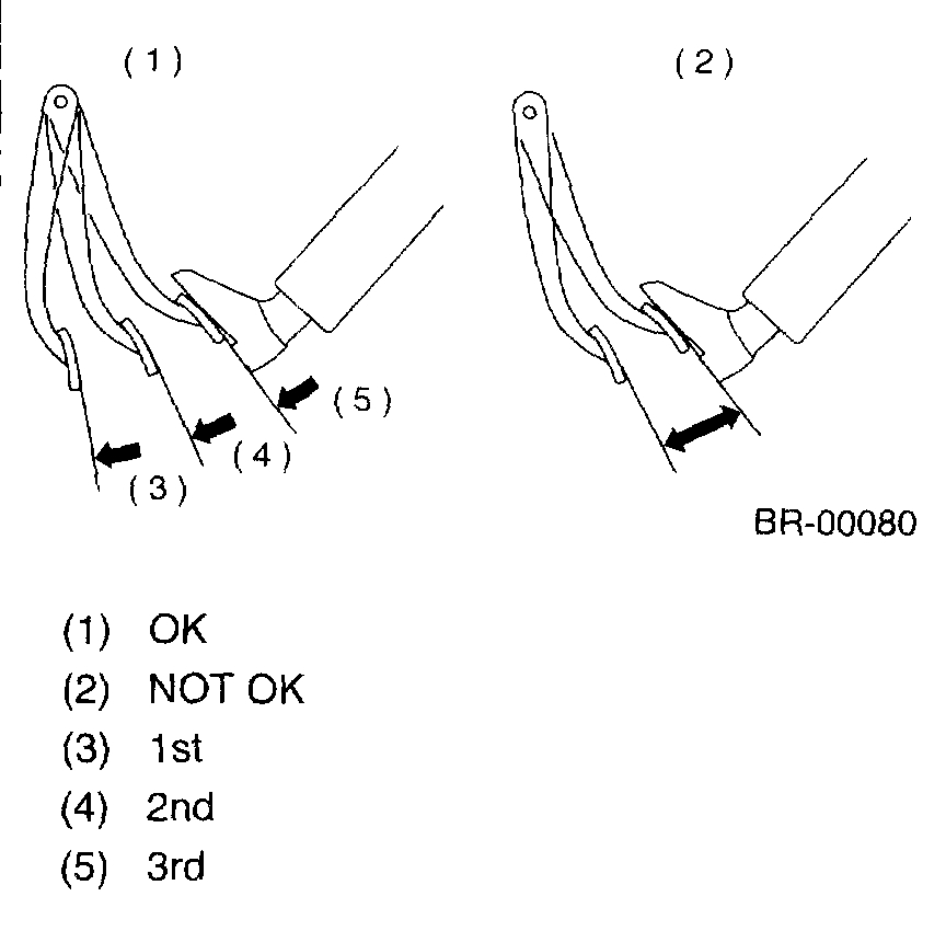
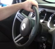
1) With the engine off, depress the brake pedal several times applying the same pedal force and make sure that the pedal height does not vary with each depression of the pedal.
2) With the brake pedal depressed, start the engine.
3) As engine starts, the brake pedal should move slightly toward the floor. If no change occurs in the pedal height, the brake booster is faulty.
NOTE: If faulty, check precisely with gauges.
Loaded air tightness check
Depress the brake pedal while engine is running, and turn off the engine while the pedal is still depressed. Keep the pedal depressed for 30 seconds; if no change occurs in the pedal height, the brake booster is functioning normally; if the pedal height increases it is faulty.
NOTE: If faulty, check precisely with gauges.
__________________________________
Here are the directions for checking with gauges. Since you have a good bit of knowledge, I am adding them.
OPERATION CHECK (WITH GAUGES)
CAUTION: When checking operation, be sure to securely apply the hand brake.
Checking with gauges
pic 3
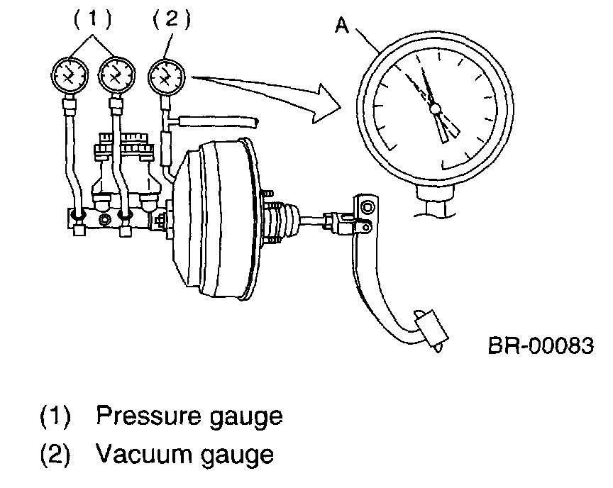
Connect gauges as shown in the figure. After bleeding air from pressure gauges, proceed to each check.
Air tightness check
pic 4
1) Start the engine and keep it running until a vacuum of 66.7 kPa (500 mmHg, 19.69 inHg) = point A is indicated on vacuum gauge Do not depress the brake pedal.
2) Stop the engine and watch the gauge. If the vacuum drop range is less than 3.3 kPa (25 mmHg, 0.98 inHg) within 15 seconds after stopping the engine, the brake booster is functioning properly.
If defective, the cause may be one of those listed below.
Check valve malfunction
Leak from vacuum hose
Leak from the shell jointed portion or stud bolt welded portion
Damaged diaphragm
Leak from valve body seal and bearing portion
Leak from plate and seal assembly portion
Leak from poppet valve assembly portion
Loaded air tightness check
pic 5
1) Start the engine and depress the brake pedal with pedal force of 196 N (20 kgf, 44 lbs.). Keep the engine running until a vacuum of 66.7 kPa (500 mmHg, 19.69 inHg) = point B is indicated on vacuum gauge while the pedal is still depressed.
2) Stop the engine and watch vacuum gauge.
If the vacuum drop range is less than 3.3 kPa (25 mmHg, 0.98 inHg) within 15 seconds after stopping the engine, brake booster is functioning properly.
If defective, refer to "AIR TIGHTNESS CHECK".
Lack of boosting action check
Turn off the engine, and set the vacuum gauge reading at "0". Then, check the fluid pressure when brake pedal is depressed. The pressure must be greater than the standard value listed.
Pic 6
Boosting action check
pic 7
Set the vacuum gauge reading at 66.7 kPa (500 mmHg, 19.69 inHg) by running engine. Then, check the fluid pressure when brake pedal is depressed. The pressure must be greater than the standard value listed.
______________________________________
If you find the booster is faulty, here are the directions for replacement.
______________________________________
2004 Subaru Impreza WRX F4-2.0L DOHC Turbo
Procedures
Vehicle Brakes and Traction Control Power Brake Assist Vacuum Brake Booster Service and Repair Procedures
PROCEDURES
Brake Booster
REMOVAL
1) Remove or disconnect the following parts at engine compartment.
1) Disconnect the connector for brake fluid level indicator.
2) Remove the brake pipes from master cylinder.
3) Remove the master cylinder installing nuts.
4) Disconnect the vacuum hose from brake booster.
2) Remove the following parts from the pedal bracket.
1) Snap pin and clevis pin
2) Four brake booster installing nuts
3) Remove the brake booster while shunning brake pipes.
NOTE:
Be careful not to drop the brake booster. Brake booster should be discarded if it has been dropped.
Use special care when handling the operating rod.
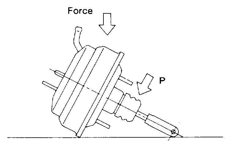
If excessive force is applied to operating rod, sufficient to cause a change in the angle in excess of ±3°, it may result in damage to the power piston cylinder.
Use care when placing the brake booster on the floor.
Do not change the push rod length. If it has been changed, reset the projected length "L" to the standard length.
Pic 8
Standard:
L = 10.05 mm (0.40 inch)
pic 9
CAUTION: If external force is applied from above when brake booster is placed in this position, the resin portion as indicated byes", may be damaged.
INSTALLATION
1) Mount the brake booster in position.
Pic 10
2) Connect the operating rod to brake pedal with clevis pin and snap pin.
Pic 11
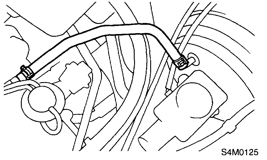
3) Connect the vacuum hose to brake booster.
4) Mount the master cylinder onto brake booster.
5) Connect the brake pipes to master cylinder.
6) Connect the electric connector for brake fluid level indicator.
Pic 12
7) Adjust the operating rod of brake booster.
Standard:
L 144.6 mm (5.69 inch)
If it is not within specified value, adjust it by adjusting the brake booster operating rod.
Pic 13
8) Measure the clearance between threaded end of stop light switch and stopper. If it is not within specified value, adjust it by adjusting the position of stop light switch.
CAUTION: Be careful not to rotate the stop light switch.
Stop light switch clearance:
A 0.3 mm (0.012 inch)
9) Apply grease to operating rod connecting pin to prevent it from wearing.
10) Bleed air from the brake system.
Tightening torque (Air bleeder screw): 8 Nm (0.8 kgf-m, 5.8 ft. Lbs.)
11) Conduct road tests to ensure brakes do not drag.
_______________________________
I hope something here is helpful. Let me know if you have other questions and what you find.
Take care,
Joe
Images (Click to make bigger)
SPONSORED LINKS
Tuesday, August 13th, 2019 AT 8:35 PM