Hi,
I looked up both part numbers and they are different. I attached them below. Chances are it will be a slight difference, but I don't recommend interchanging them.
3.0L Automatic Right with ABS
434100607084
2.2L Automatic Right with ABS
434100606084
_______________________________
I don't know if it will help, but here are the directions for replacement. This is for a 3.0L as indicated in your heading. The pics below correlate with the directions.
_______________________________
1999 Toyota Camry LE Sedan V6-3.0L (1MZ-FE)
Removal and Installation
Vehicle Transmission and Drivetrain Drive Axles, Bearings and Joints Axle Shaft Assembly Axle Shaft Service and Repair Procedures Axle Shaft Assembly, Constant Velocity Type Removal and Installation
REMOVAL AND INSTALLATION
REMOVAL
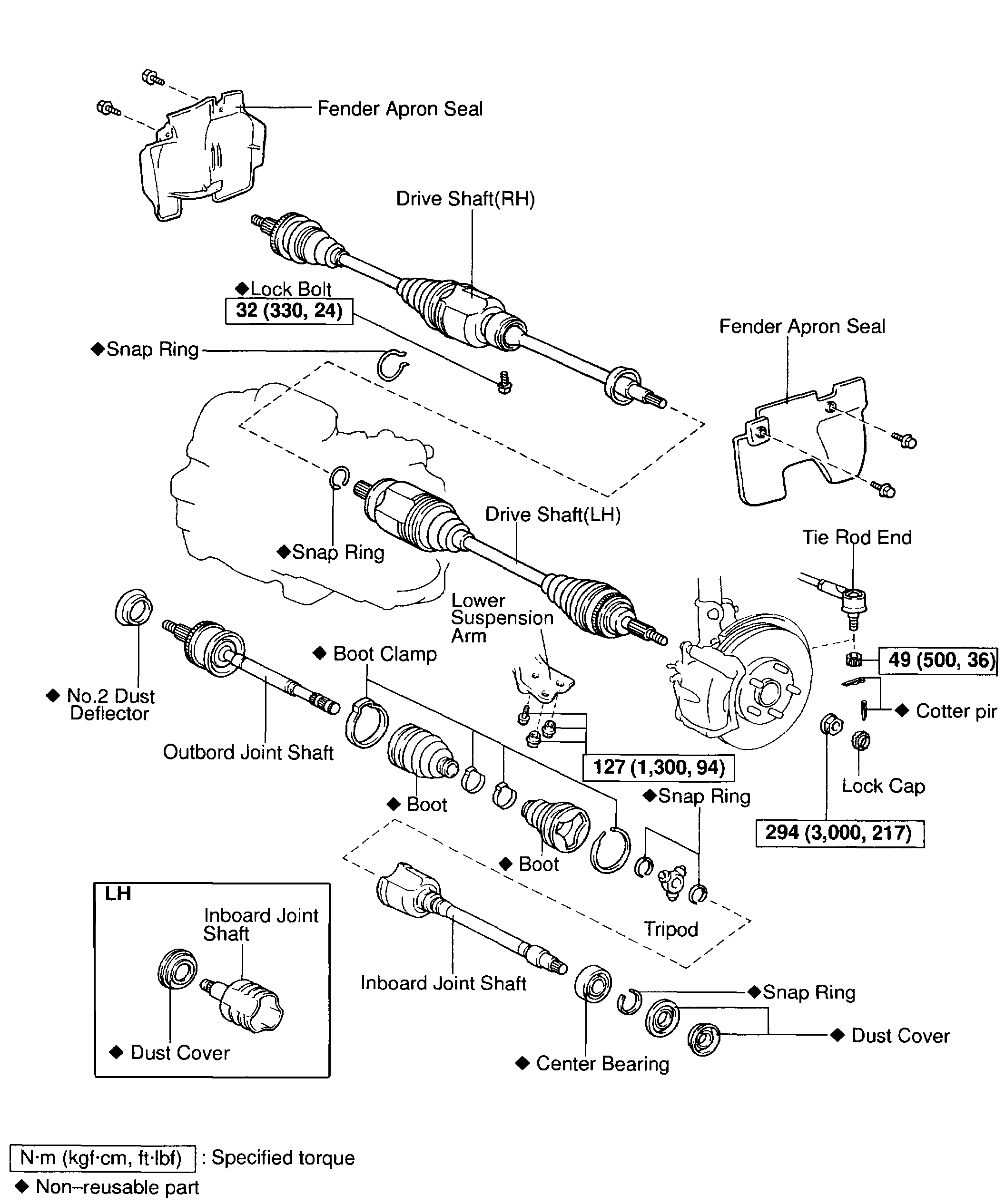
pic 1
With 5S-FE
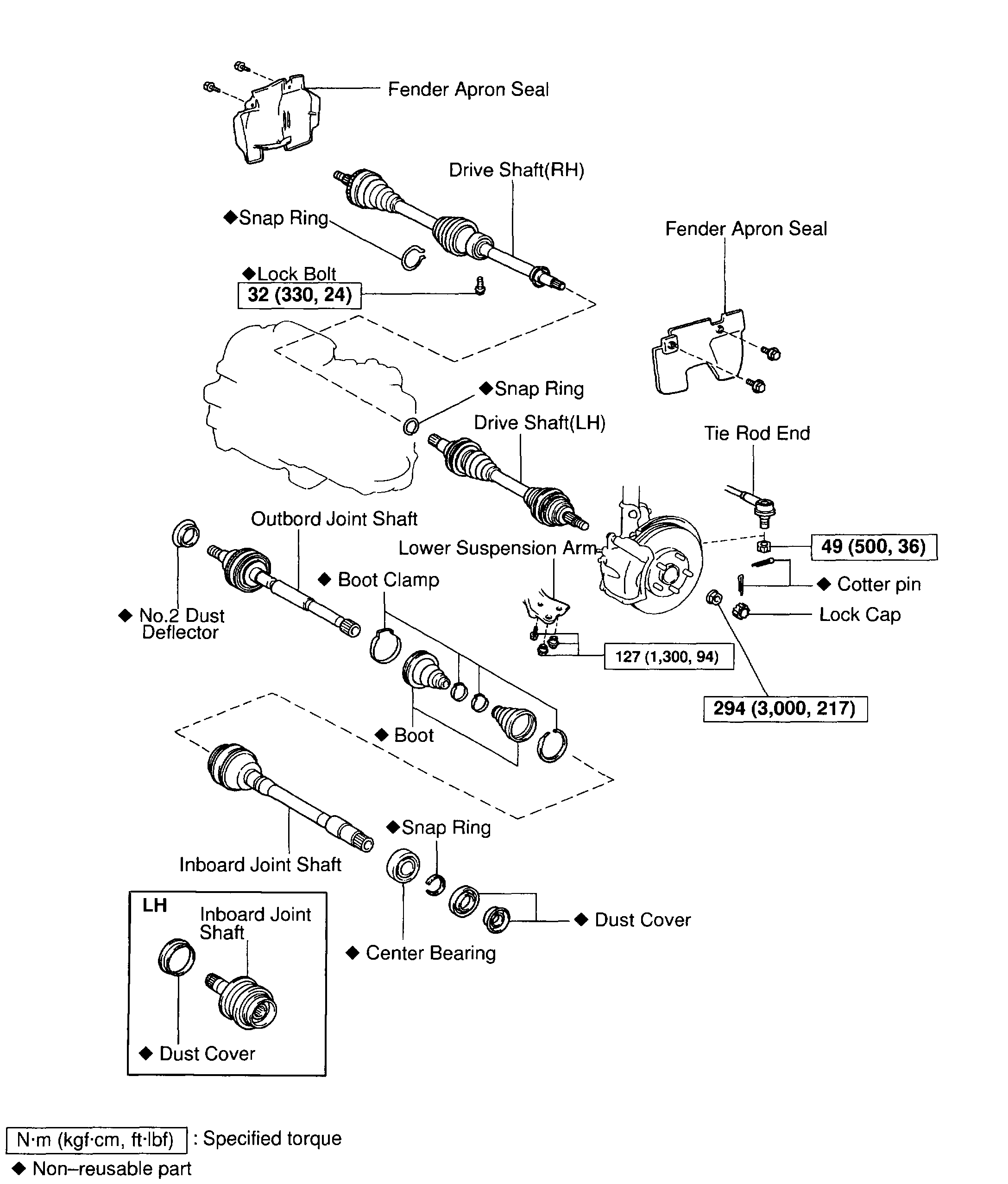
pic 2
With 1MZ-FE
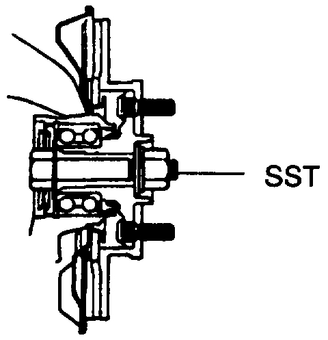
NOTICE: The hub bearing could be damaged if it is subjected to the vehicle weight, such as when moving the vehicle with the drive shaft removed.
Therefore, if it is absolutely necessary to place the vehicle weight on the hub bearing, first support it with Special Service Tool (SST).
Pic 3
(SST) 09608-16042 (09608-02021, 09608-02041)
1. REMOVE FRONT WHEEL AND FRONT FENDER APRON SEAL
Torque: 103 Nm (1,050 kgf-cm, 76 ft. Lbs.)
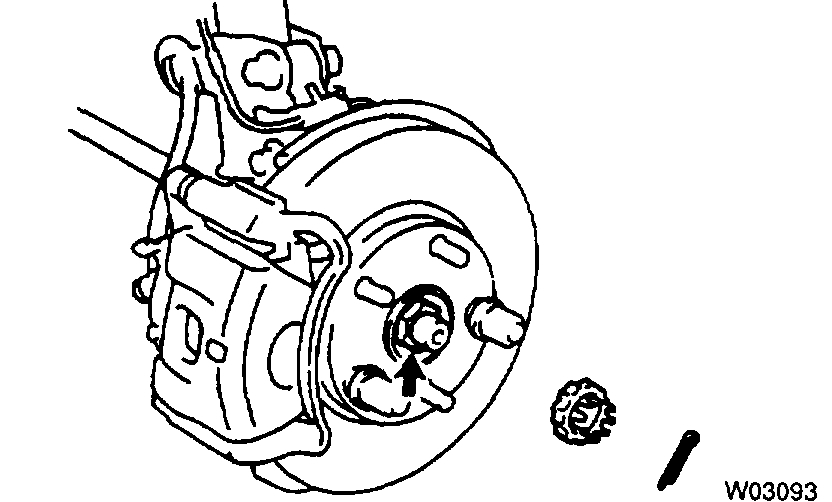
pic 4
2. REMOVE DRIVE SHAFT LOCK NUT
a. Remove the cotter pin and lock cap.
B. With applying the brakes, remove the nut.
Torque: 294 Nm (3,000 kgf-cm, 217 ft. Lbs.)
3. DRAIN GEAR OIL (M/T) or ATF (A/T)
4. DISCONNECT TIE ROD END FROM STEERING KNUCKLE
5. DISCONNECT LOWER BALL JOINT FROM LOWER SUSPENSION ARM
pic 5
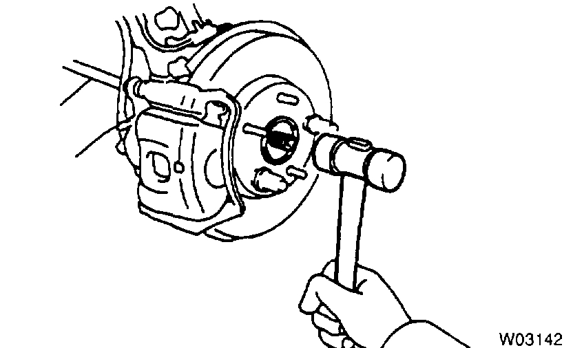
6. DISCONNECT DRIVE SHAFT FROM AXLE HUB
a. Using a plastic hammer, disconnect the drive shaft from the axle hub.
NOTICE: Cover the drive shaft boot with cloth to protect it from damage.
B. Push the front axle hub toward the outside of the vehicle, and separate the drive shaft from the axle hub.
Pic 6
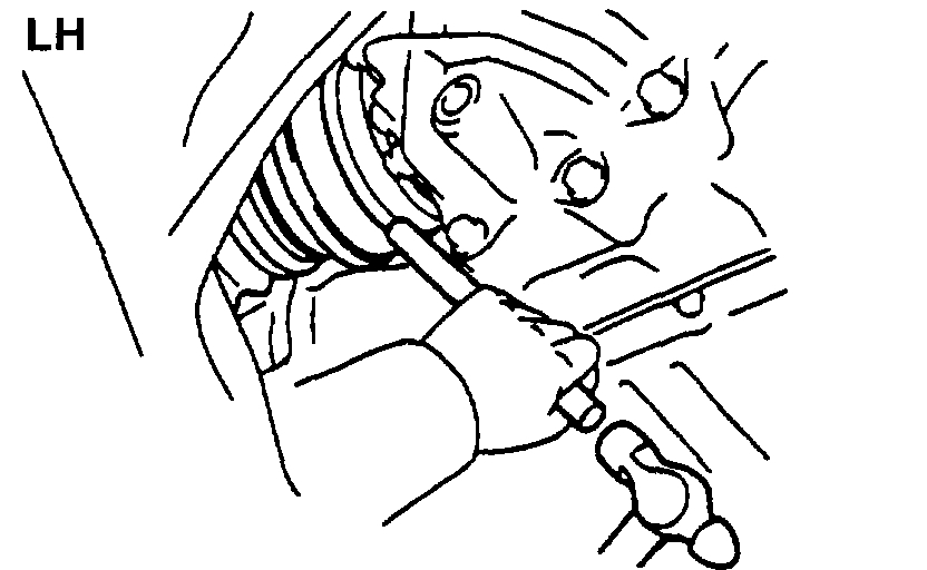
7. REMOVE LEFT-HAND DRIVE SHAFT
a. Using a brass bar and hammer, remove the drive shaft.
HINT: At the time of installation, please refer to the following items.
- Coat gear oil to the inboard joint shaft and differential case sliding surface.
- Before installing the drive shaft, set the snap ring with its opening side facing downward.
- Whether or not the inboard joint shaft is making contact with the pinion shaft can be known by the sound or feeling when driving it in.
- After installation, check that there is 2 - 3 mm (0.08 - 0.12 inch) of play in the axial direction.
- After installation, check that the drive shaft cannot be removed by hand.
B. Using a screwdriver, remove the snap ring from the in board joint shaft.
Pic 7
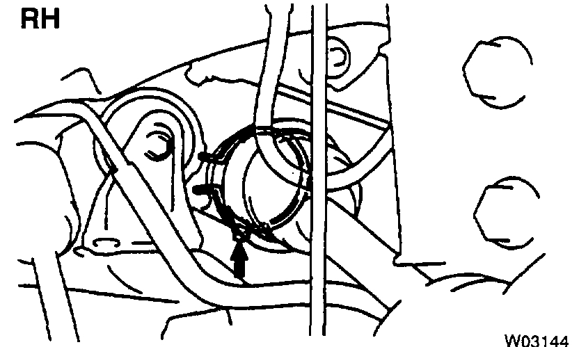
8. REMOVE RIGHT-HAND DRIVE SHAFT
a. Remove the bearing lock bolt.
Torque: 32 Nm (330 kgf-cm, 24 ft. Lbs.)
b. Using pliers, remove the snap ring and drive shaft.
HINT: At the time of installation, coat gear oil to the inboard joint shaft and differential case sliding surface.
INSTALLATION
Installation is in the reverse order of removal.
AFTER INSTALLATION, CHECK ANTI-LOCK BRAKE SYSTEM (ABS) SPEED SENSOR SIGNAL AND FRONT WHEEL ALIGNMENT
________________________________
I hope this helps. Let me know if you have other questions.
Take care and God Bless,
Joe
Images (Click to make bigger)
SPONSORED LINKS
Tuesday, February 23rd, 2021 AT 8:10 PM