If you had no problem before getting bad gas, I suspect water.. Test TPS like this:
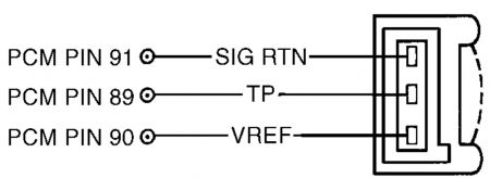
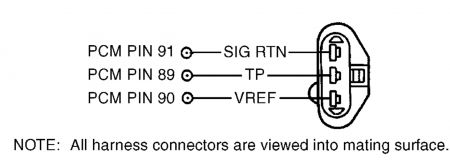
4) Check For Stuck TP Sensor Turn ignition off. Using scan tool, select TP V PID from PID/DATA monitor menu. While observing TP V PID, slowly move throttle through range from closed to wide open throttle. If PID value indicates any sudden drop to less than .49 volt, go to next step. If PID value increases and decreased gradually and smooth, go to step 20). 5) Check VREF Circuit Voltage Disconnect TP sensor connector. Turn ignition on. Measure voltage between VREF and SIG RTN terminals at TP sensor wiring harness connector. See Fig. 80 or Fig. 81 . If voltage is 4-6 volts, go to next step. If voltage is not 4-6 volts, reconnect sensor and go to TEST C . Fig. 80: Identifying TP Sensor Circuits & Connector Terminals (Contour 2.0L, Cougar 2.0L & Mystique 2.0L) Courtesy of FORD MOTOR CO. Fig. 81: Identifying TP Sensor Circuits & Connector Terminals (Except Contour 2.0L, Cougar 2.0L & Mystique 2.0L) Courtesy of FORD MOTOR CO. 6) Check TP Circuit Resistance Turn ignition off. Disconnect PCM 104-pin connector. Inspect connector for loose, damaged or corroded terminals and repair as necessary. Measure resistance between PCM connector pin No. 89 (TP) and TP terminal at TP sensor wiring harness connector. If resistance is less than 5 ohms, go to next step. If resistance is 5 ohms or more, repair open in TP circuit. 7) Check TP Sensor Signal To PCM Reconnect PCM connector. Start engine and idle for 2 minutes. While slowly opening throttle, measure voltage between PCM connector pin No. 89 (TP) and 91 (SIG RTN). If at any time voltage enters .17-.40 volt range, replace TP sensor. If voltage does not enter .17-.40 volt range, repeat QUICK TEST . If DTC P1120 is still present, go to step 20). 8) DTC P0123 Or P0124 These DTCs indicate TP signal is more than self-test maximum. Possible causes for this fault are: � � � TP sensor not seated correctly. � � � Faulty TP sensor. � � � TP circuit shorted to VREF or VPWR. � � � VREF circuit shorted to VPWR. � � � Open in SIG RTN circuit. � � � Faulty PCM. Turn ignition off. Disconnect TP sensor connector. Inspect connector for loose, damaged or corroded terminals and repair as necessary. Turn ignition on. Using scan tool, select TP V PID for PID/DATA monitor menu. If PID voltage is .17 volt or more, go to step 20). If PID voltage is less than .17 volt, go to next step. 9) Check VREF Circuit Voltage Measure voltage between VREF and SIG RTN terminals at TP sensor wiring harness connector. If voltage is 4-6 volts, go to next step. If voltage is not 4-6 volts, reconnect components and go to TEST C . 10) Check TP Circuit For Short To Power Turn ignition off. Leave TP sensor disconnected. Disconnect PCM 104-pin connector. Inspect connector for loose, damaged or corroded terminals and repair as necessary. Measure resistance between PCM connector pin No. 89 (TP) and pins No. 71 (VPWR) and 90 (VREF). If any resistance reading is 10,000 ohms or less, repair short circuit. If both resistance readings are more than 10,000 ohms, replace PCM. 11) DTC P0122 This DTC indicates TP signal is less than self-test minimum of .17 volt. Possible causes for this fault are: � � � TP sensor not seated correctly. � � � Faulty TP sensor. � � � Open TP or VREF circuit. � � � TP circuit shorted to SIG RTN or PWR GND. � � � Faulty PCM. Turn ignition off. Disconnect TP sensor connector. Inspect connector for loose, damaged or corroded terminals and repair as necessary. Connect a jumper wire between VREF and TP terminals at TP wiring harness connector. Turn ignition on. Using scan tool, select TP V PID from PID/DATA monitor menu. If PID voltage is more than 4.60 volts, replace TP sensor. If PID voltage is 4.60 volts or less, remove jumper wire and go to next step. 12) Check VREF Circuit Voltage Turn ignition on. Measure voltage between VREF and SIG RTN terminals at TP sensor wiring harness connector. If voltage is 4-6 volts, go to next step. If voltage is not 4-6 volts, reconnect sensor and go to TEST C . NOTE: An intermittent fault can cause a Continuous Memory DTC P0122. If a Continuous Memory DTC P0122 is still present after performing steps 11-14, go to step 20). NOTE: If communication link error is displayed, remove jumper wire and go to step 14). 13) Check TP Circuit Resistance Turn ignition off. Leave TP sensor disconnected. Disconnect PCM 104-pin connector. Inspect connector for loose, damaged or corroded terminals and repair as necessary. Measure resistance between PCM connector pin No. 89 (TP) and TP terminal at TP sensor wiring harness connector. If resistance is less than 5 ohms, go to next step. If resistance is 5 ohms or more, repair open in TP circuit. 14) Check TP Circuit For Short To SIG RTN Or PWR GND Disconnect scan tool Data Link Connector (DLC). Measure resistance between PCM connector pin No. 89 (TP) and pins No. 91 (SIG RTN), 24 or 103 (PWR GND). If any resistance reading is 10,000 ohms or less, repair TP circuit short to SIG RTN or PWR GND. If both resistance readings are more than 10,000 ohms, replace PCM. 15) Continuous Memory DTC P1121 This DTC indicates TP signal is inconsistent with MAF sensor signal. Possible causes for this fault are: � � � TP sensor not seated correctly. � � � Faulty TP sensor. � � � Air leak between MAF sensor and throttle body. Attempt to start engine. If engine will start, go to next step. If engine will not start, check for cracks or openings in air induction system between MAF sensor and throttle body. If air induction system is okay, go to TEST A . 16) Check Operation Of TP Sensor Turn ignition on. Using scan tool, select TP V PID from PID/DATA monitor menu. While observing PID V, slowly move throttle through range from closed position to wide open throttle. If PID voltage changes from .49-4.65 volts, go to next step. If PID voltage does not change from .49-4.65 volts, replace TP sensor. 17) Check Operation Of TP Sensor While Driving Vehicle Drive vehicle (vary throttle position) while accessing TP V PID and LOAD PID. If TP V PID voltage is 2.44 volts or less and LOAD PID value is more than 30 percent, go to next step. If TP PID voltage is more than 2.44 volts and LOAD PID value is less than 30 percent, check for cracks or openings in air induction system between MAF sensor and throttle body. If air induction system is okay, replace TP sensor. 18) Check TP Sensor Low With Engine Under Load Start engine and allow to idle. If engine does not start, go to TEST A . Drive vehicle (vary throttle position) near higher gears (preferably overdrive) while accessing TP V PID and LOAD PID. If TP V PID is .24 volt or more and LOAD PID is less than 60 percent, fault is intermittent and cannot be duplicated at this time. Testing is complete. If TP V PID is less than .24 volt and LOAD PID is 60 percent or more, tighten TP sensor (if necessary). Clear DTCs. Perform test drive utilizing all phases of vehicle operation. Perform QUICK TEST . If DTC Continuous Memory P1121 is still present, replace MAF sensor. 20) Continuous Memory DTC P1120 Or P1125 These DTCs indicate TP signal went to less than .49 volt or more than 4.60 volts sometime during the last 80 drive cycles. Possible causes for this fault are: � � � Faulty TP sensor wiring harness or connector. � � � Faulty TP sensor. With scan tool connected, start engine and allow to idle. Raise engine speed to 1500 RPM for 5 seconds and return to idle. Using scan tool, select TP V PID from PID/DATA monitor menu. While observing PID, lightly tap on TP sensor to simulate road shock. Wiggle sensor connector and wiring harness. If TP PID voltage stays within normal operating range (.49-4.60 volts), go to next step. If TP PID voltage goes out of range, inspect TP sensor installation. Repair as necessary and retest. If TP sensor installation is okay, replace TP sensor. 21) Check Wiring Harness Between TP Sensor & PCM Turn ignition off. Disconnect PCM 104-pin connector. Inspect connector for loose, damaged or corroded terminals and repair as necessary. Reconnect PCM connector. Using scan tool, select TP V PID from PID/DATA monitor menu. While observing PID, wiggle small sections of wiring harness starting at the TP sensor working toward PCM. If PID voltage stays within normal operating range (.49-4.60 volts), problem is intermittent and cannot be identified at this time. Go to TEST Z . If PID voltage goes out of range, isolate fault and repair as necessary. 22) DTC P0121: Verify KOER On-Demand Self-Test Completion Start engine and allow to idle. Using scan tool, enter KOER ON-DEMAND SELF-TEST . If DTC P0121 is present or KOER on-demand self-test cannot be completed, go to next step. If KOER on-demand self-test is complete and DTC P0121 is not present, problem is intermittent and cannot be identified at this time. 23) Attempt To Recreate DTC With engine idling, place gear selector in Drive or Reverse. If KOER on-demand self-test completes, go to next step. If KOER on-demand self-test does not complete, turn ignition off and wait for 15 seconds. Start engine and allow to idle. Enter KOER ON-DEMAND SELF- TEST . If DTC P0121 is present or KOER on-demand self-test does not complete, go to next step. If KOER on-demand self-test completes and DTC P0121 is not present, problem is intermittent and cannot be identified at this time. 24) Check For Open Circuit Turn ignition off. Disconnect TP sensor connector. Disconnect PCM 104-pin connector. Inspect connector for loose, damaged or corroded terminals and repair as necessary. Measure resistance of TP circuit between TP sensor wiring harness connector and PCM connector pin NOTE: A break in step numbering sequence occurs at this point. Procedure skips from step 18) to step 20). No test procedures have been omitted. No. 89. Also measure resistance of SIG RTN circuit between TP sensor wiring harness connector and PCM connector pin No. 91. If both resistance readings are less than 5 ohms, replace TP sensor. If any resistance reading is 5 ohms or more, repair open circuit.
Thursday, August 19th, 2010 AT 2:48 AM