The indicated position of the transmission floor mounted selector lever is transferred to the transmission through the cable and down to the manual control lever on the transmission.
Shift Interlock System
The brake/shift interlock mechanism is used on vehicles equipped with an automatic transmission. This system is used to prevent shifting from PARK unless the brake pedal is depressed. The brake/shift interlock system consists of an actuator attached to the key interlock assembly and necessary wiring. The shift lock actuator is energized when the ignition switch is turned to the RUN position, locking the floor mounted transmission range selector lever in the PARK position. When the brake pedal is depressed, the shift lock actuator is deactivated and the floor mounted transmission range selector lever can be moved out of the PARK position.
Pinpoint Test A: The Shift Interlock System Does Not Release/Lock Correctly
A1 TEST THE BRAKE LIGHTS
Key in ON position.
Apply the brake pedal and observe the stoplamps.
Do the stoplamps illuminate?
Yes : GO to A2.
No : REFER to EXTERIOR LIGHTING .
A2 CHECK CIRCUIT 511 (LG) FOR AN OPEN
Key in OFF position.
Disconnect: Shift Lock Actuator C2127.
Measure the voltage between shift lock actuator C2127-3, circuit 511 (LG), harness side and ground while depressing and releasing the brake pedal.
Fig. 1: Measuring Voltage Between Shift Lock Actuator C2127-3, Circuit 511 Harness Side And Ground
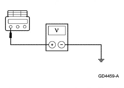
Is the voltage greater than 10 volts with the brake pedal depressed and 0 volts with the brake pedal released?
Yes : GO to A3.
No : REPAIR the circuit. TEST the system for normal operation.
A3 CHECK CIRCUIT 294 (WH/LB) FOR AN OPEN
Key in ON position.
Measure the voltage between shift lock actuator C2127-1, circuit 294 (WH/LB), harness side and ground.
Fig. 2: Measuring Voltage Between Shift Lock Actuator C2127-1, Circuit 294 Harness Side And Ground
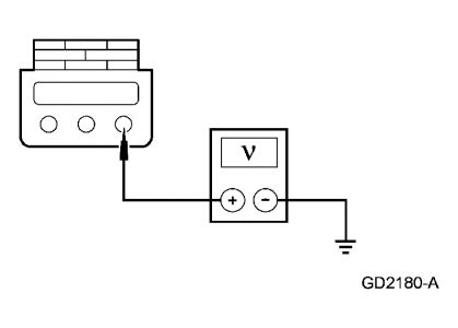
Is the voltage greater than 10 volts?
Yes : GO to A4.
No : REPAIR the circuit. TEST the system for normal operation.
A4 TEST CIRCUIT 1205 (BK) FOR AN OPEN
Measure the resistance between shift lock actuator C2127-2, circuit 1205 (BK), harness side and ground.
Fig. 3: Measuring Resistance Between Shift Lock Actuator C2127-2, Circuit 1205 Harness Side And Ground
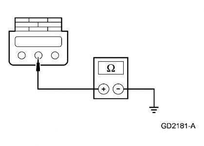
Is the resistance less than 5 ohms?
Yes : INSTALL a new shift lock actuator. REFER to BRAKE SHIFT INTERLOCK ACTUATOR. TEST the system for normal operation.
No : REPAIR the circuit. TEST the system for normal operation.
SPONSORED LINKS
Wednesday, January 28th, 2009 AT 8:41 PM

