Removal
Disconnect negative battery cable. On vehicles with dual batteries, see DUAL BATTERIES under MISCELLANEOUS. Release fuel pressure. See FUEL SYSTEM PRESSURE RELEASE .
Remove the valve cover.
Left
Remove air cleaner assembly. See AIR CLEANER under AIR INDUCTION SYSTEMS.
Remove turbocharger intake tube. See TURBOCHARGER INTAKE TUBE under AIR INDUCTION SYSTEMS.
Remove injection driver module. See INJECTOR DRIVER MODULE under COMPUTERIZED ENGINE CONTROLS. Remove injector driver module mounting bracket. See Fig. 60 .
Disconnect glow plug harness connector and position aside. Remove oil level tube retaining nut and position tube aside. See Fig. 61 .
Noting position of stud bolts, remove valve cover. See Fig. 62 .
Right
Remove right fender splash shield. Loosen clamps at charge air cooler and turbocharger. Remove charge air tube. See Fig. 2 .
Disconnect wiring retainer from valve cover stud bolt. Remove glow plug control module. See GLOW PLUG MODULE under COMPUTERIZED ENGINE CONTROLS.
On vehicles with automatic transmission, remove transmission fluid level indicator. Remove retaining nut and disconnect transmission fluid fill tube from stub tube and position it aside. See Fig. 28 .
Noting position of stud bolts, remove valve cover. See Fig. 62 .
Disconnect fuel injector electrical connector. See Fig. 63 .
Using Quick Release Coupling Disconnect Tool, disconnect high pressure oil rail supply line at high pressure oil rail. See Fig. 64 .
Remove high pressure oil rail bolts and remove high pressure oil rail. See Fig. 65 .
Using High Pressure Line Disconnect Tool, disconnect and remove the high pressure oil supply line. See Fig. 66 .
Using a 19-mm socket, push fuel injector electrical connector out of rocker arm carrier. See Fig. 67 .
NOTE:There is no need to drain fuel rail. If engine oil is found in the engine coolant or engine coolant is found in the combustion chambers, new injector sleeves may need to be installed. See FUEL INJECTOR SLEEVE .
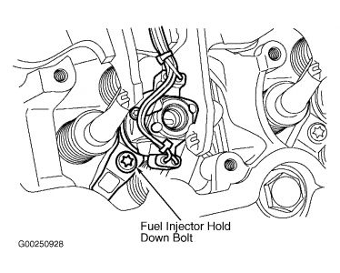
Remove fuel injector hold-down bolt, fuel injector hold down and fuel injector. See Fig. 68 .
Installation
CAUTION:If fuel injector oil inlet "D" ring is damaged, a new fuel injector must be installed.
Install new "O" rings and copper washer on fuel injector. Lubricate fuel injector and "O" rings liberally with clean engine oil.
Install fuel injector, fuel injector hold-down and bolt. See Fig. 68 . Tighten to specification. See TORQUE SPECIFICATIONS .
Install fuel injector electrical connector into rocker carrier.
Apply engine oil to top fuel injector "O" rings. See .
Install high pressure oil rail. Install high pressure oil rail bolts finger tight. Tighten bolts in proper sequence. See Fig. 71 . Tighten bolts to specification TORQUE SPECIFICATIONS . Install the high pressure oil line.
Install the valve cover.
Left
Install a NEW valve cover gasket if necessary. Install valve cover and valve cover bolts in position noted in removal process. Tighten bolts to specification. See TORQUE SPECIFICATIONS .
Place oil level tube in position and install retaining nut. Connect glow plug harness connector. See Fig. 61 .
Install injector driver module mounting bracket. See Fig. 60 . Tighten bolts to specification. See TORQUE SPECIFICATIONS . Install injection driver module. See INJECTOR DRIVER MODULE under COMPUTERIZED ENGINE CONTROLS.
Install turbocharger intake tube. See TURBOCHARGER INTAKE TUBE under AIR INDUCTION SYSTEMS.
Install air cleaner assembly. See AIR CLEANER under AIR INDUCTION SYSTEMS.
Right
Install a NEW valve cover gasket if necessary. Install valve cover and valve cover bolts in position noted in removal process. See Fig. 62 . Tighten bolts to specification. See TORQUE SPECIFICATIONS .
Install glow plug control module. See GLOW PLUG MODULE under COMPUTERIZED ENGINE CONTROLS. Connect wiring retainer to valve cover stud bolt.
Working from outside the right wheel area, engage transmission fluid fill tube to stub tube. Install transmission fluid fill tube retainer nut. Tighten to specification. See TORQUE SPECIFICATIONS .
Install charge air tube. Tighten clamps at charge air cooler and turbocharger. See Fig. 2 . Remove right fender splash shield.
Connect negative battery cable. On vehicles with dual batteries, see DUAL BATTERIES under MISCELLANEOUS.
Fuel Injector Hold-Down Bolt24 Ft/Lbs (33)N.m
Nov 27, 2008 at 9:27 PM
