Before removing the oil pump, the timing chains need to be removed. I will start with them and then follow up with the pump. The attached pictures correlate with the directions.
_____________________________________________________________
2003 Ford Truck F 150 2WD Pickup V8-5.4L Prop SOHC VIN Z
Timing Drive Components
Vehicle Engine, Cooling and Exhaust Engine Timing Components Timing Chain Service and Repair Removal and Replacement Timing Drive Components
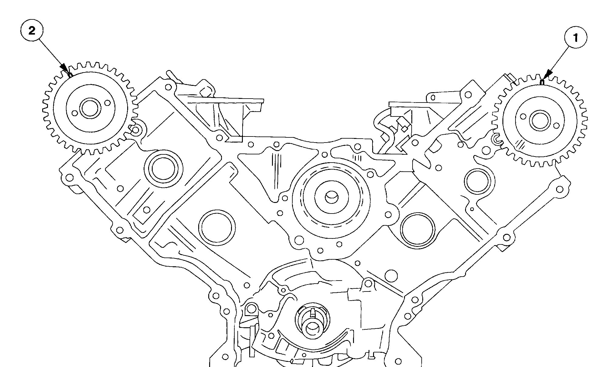
TIMING DRIVE COMPONENTS
Timing Drive Components-Windsor Engine (5.4L)
imageOpen In New TabZoom/Print
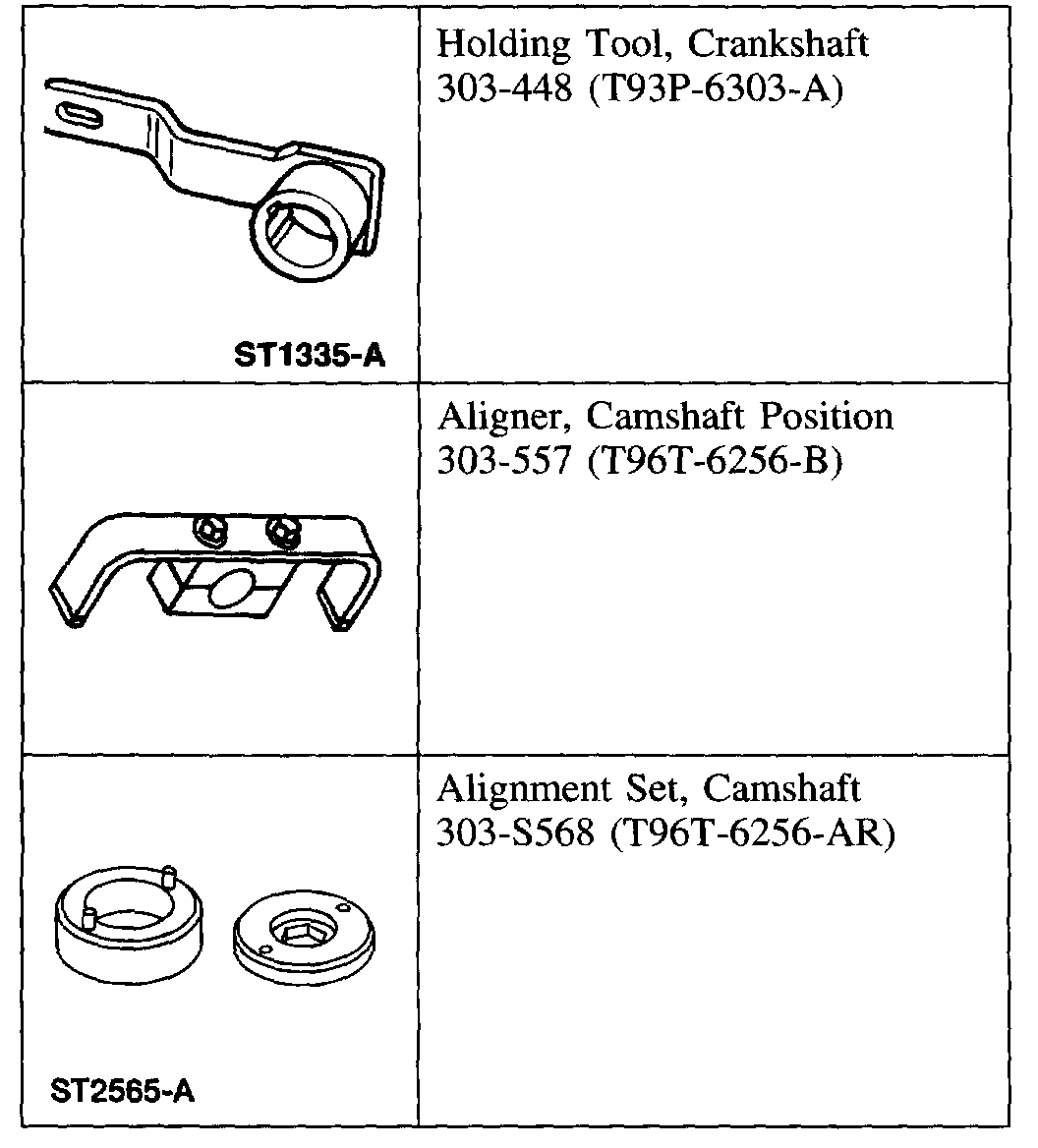
Special Tool(s)
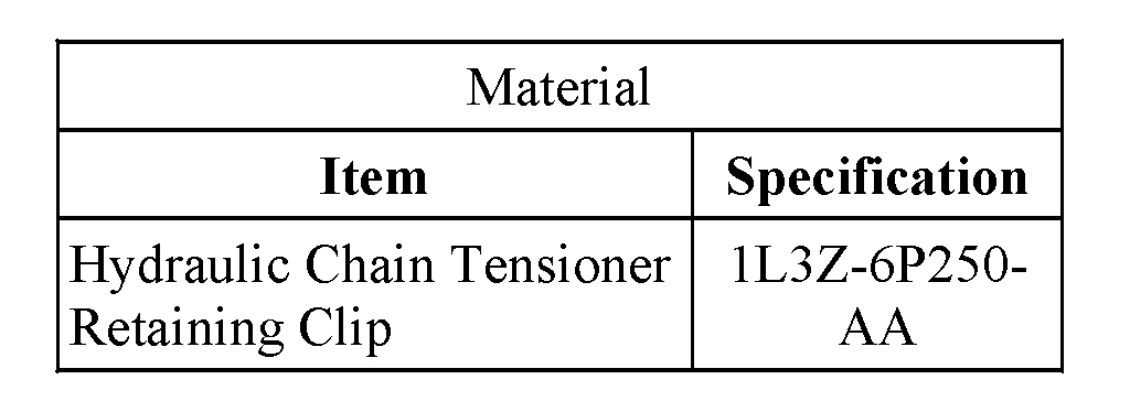
Material
pic 1
Removal
CAUTION: Since the engine is not free-wheeling, the timing procedures must be followed exactly or piston and valve damage can occur.
1. Remove the engine front cover.
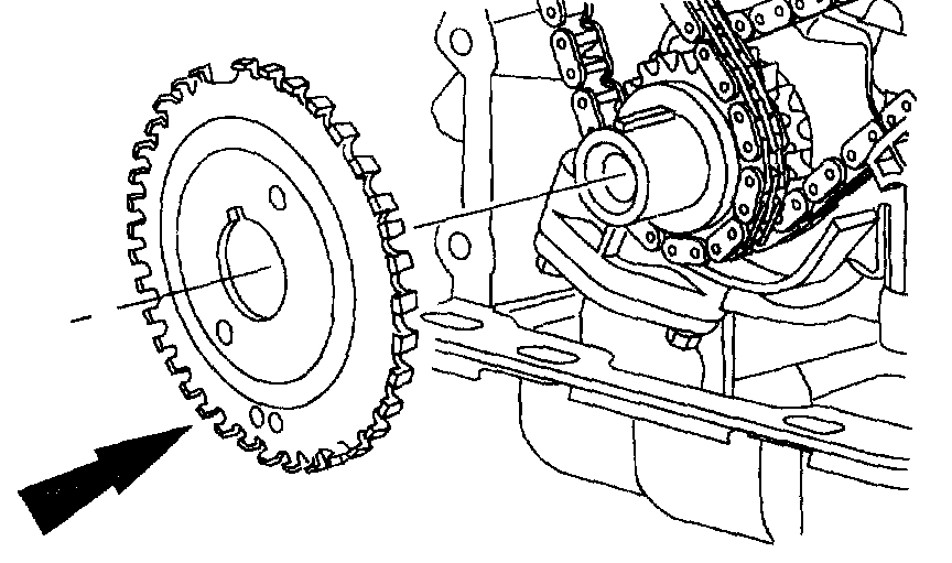
Pic 2
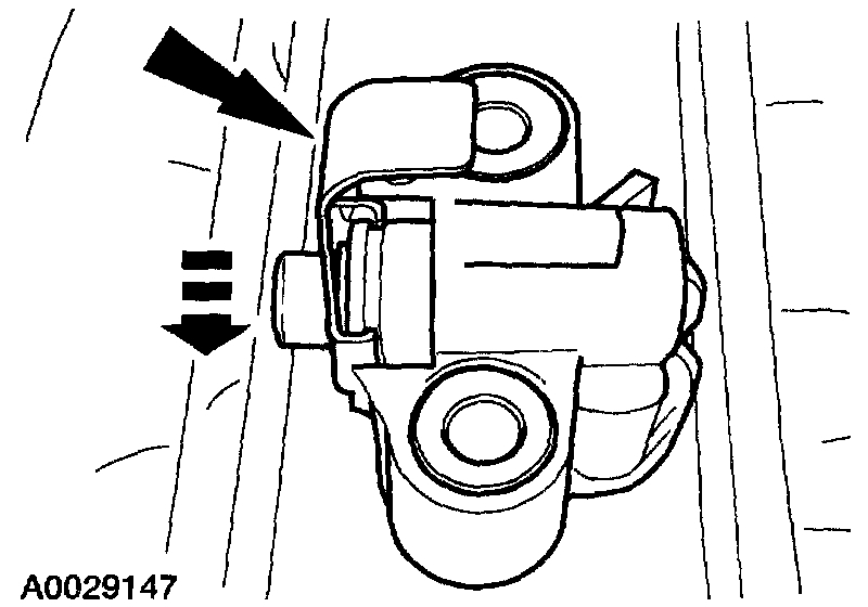
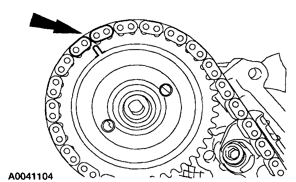
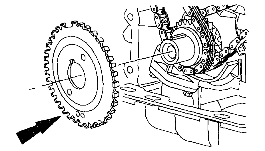
2. Remove the crankshaft sensor ring from the crankshaft.
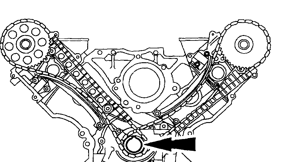
Pic 3
3. CAUTION: Unless otherwise instructed, at no time when the timing chains are removed and the cylinder heads are installed is the crankshaft or camshaft to be rotated, Severe piston and valve damage will occur.
Position the crankshaft with the keyway at the 12 o'clock position.
Pic 4
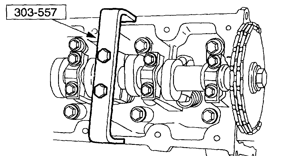
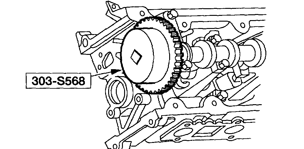
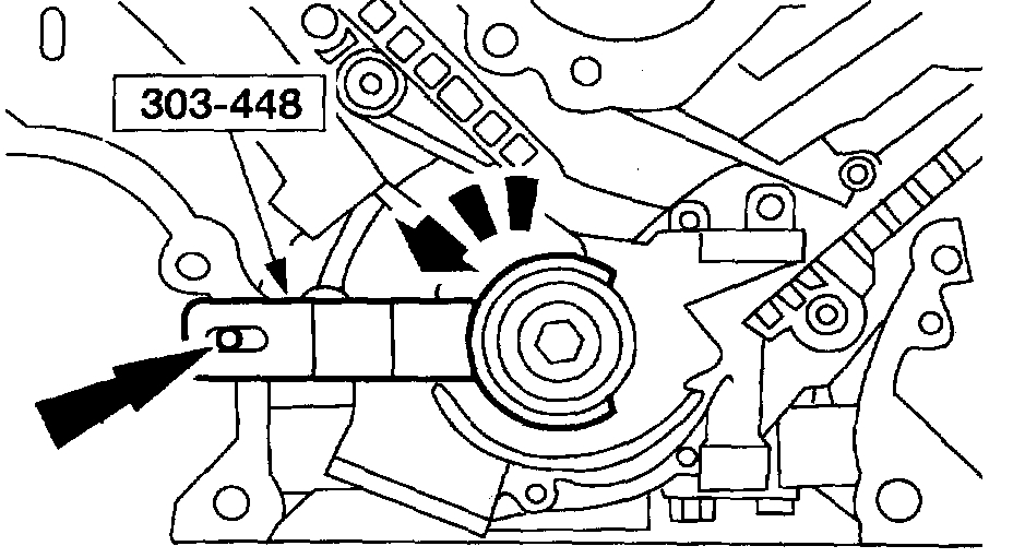
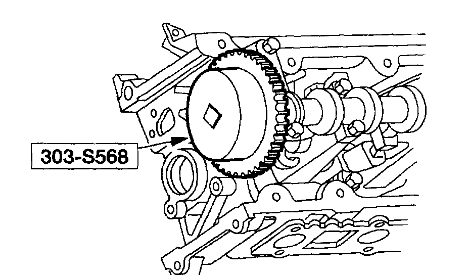
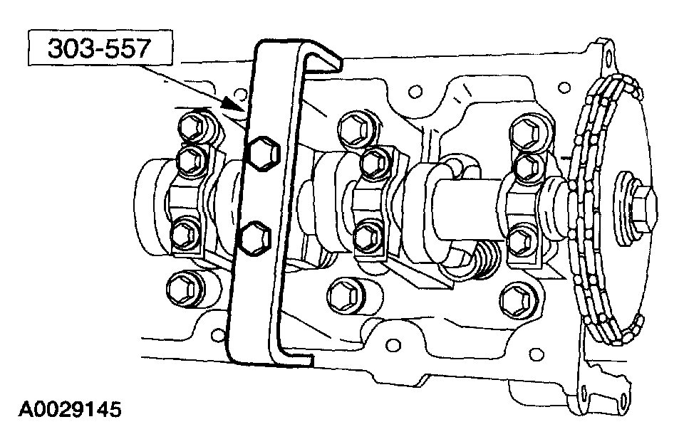
4. Install and fully tighten the special tools on both camshafts.
Pic 5
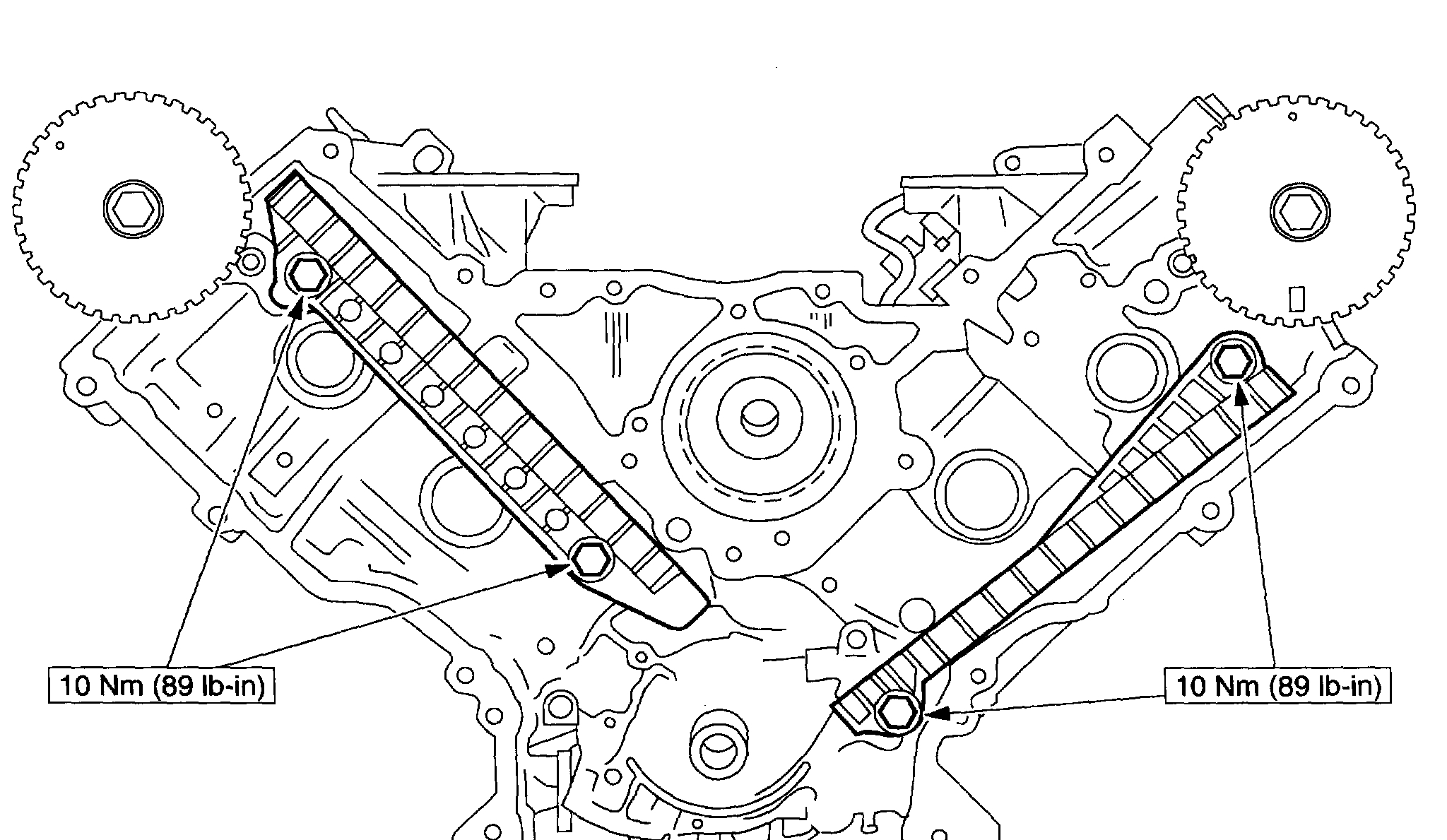
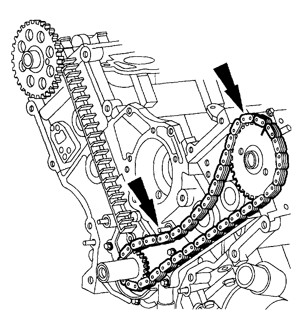
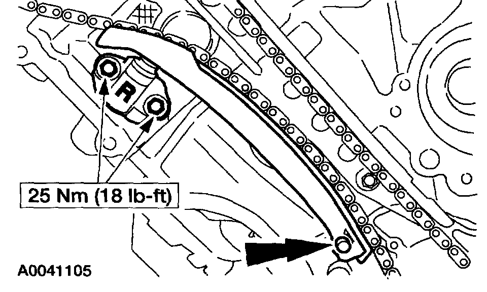
5. Remove the timing chain tensioning system from both timing chains.
1 Remove the bolts.
2 Remove the timing chain tensioners.
3 Remove the timing chain tensioner arms.
Pic 6
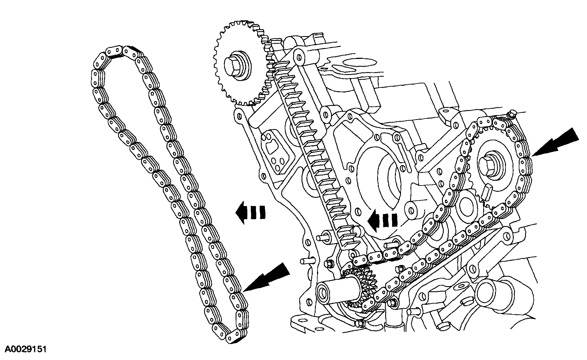
6. CAUTION: Unless otherwise instructed, at no time when the timing chains are removed and the cylinders heads are installed is the crankshaft or camshaft to be rotated. Severe piston and valve damage will occur.
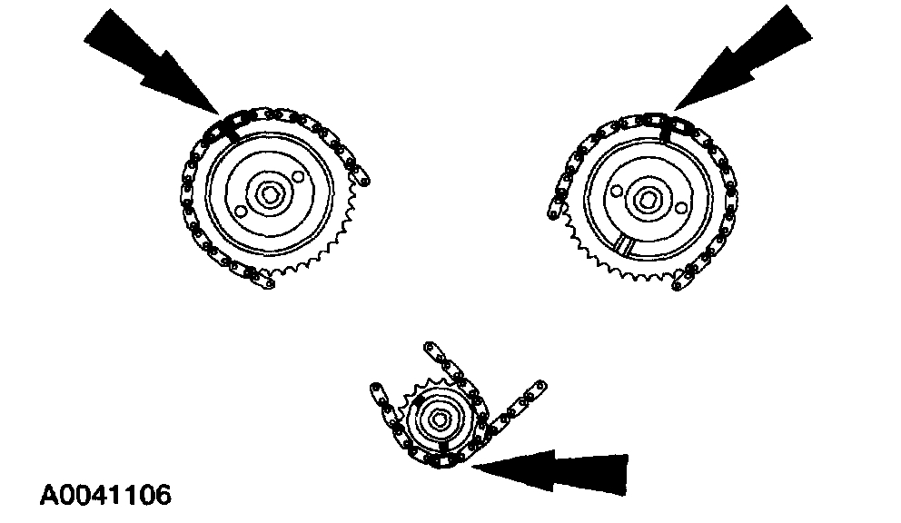
Remove the RH and LH timing chains and the crankshaft sprocket.
- Remove the RH timing chain from the camshaft sprocket.
- Remove the RH timing chain from the crankshaft sprocket.
- Remove the LH timing chain from the camshaft sprocket.
- Remove the LH timing chain and crankshaft sprocket.
Pic 7
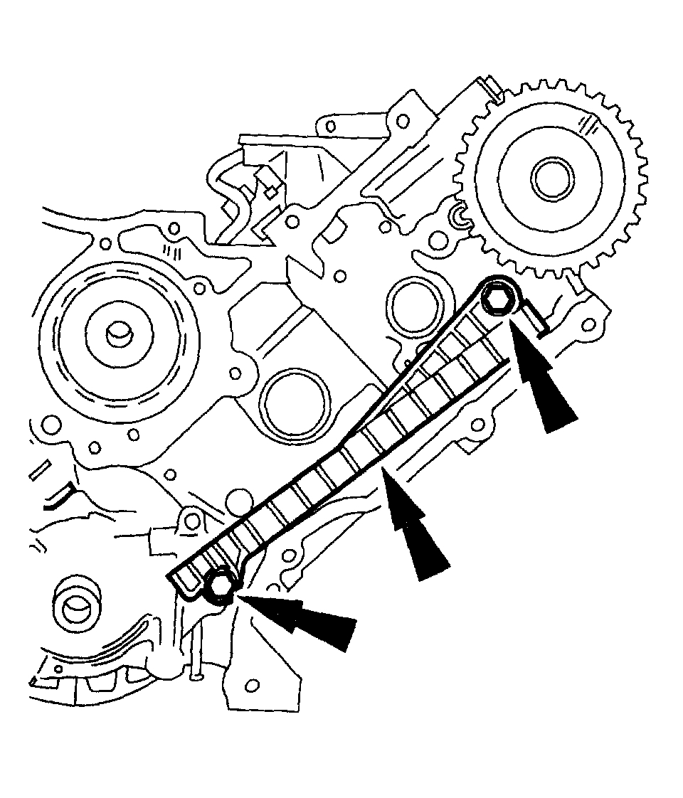
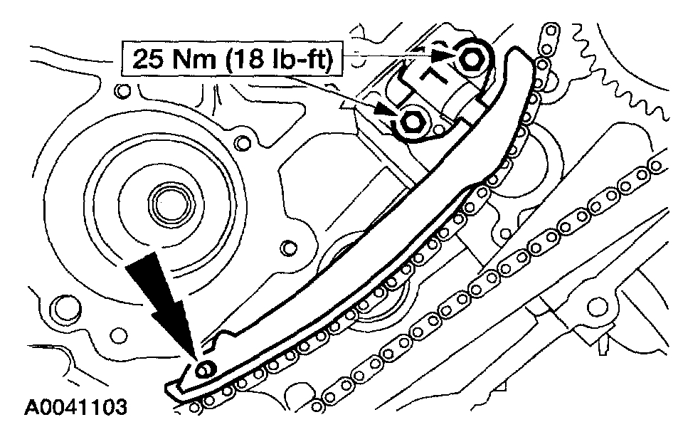
7. Remove both timing chain guides.
- Remove the bolts.
- Remove both timing chain guides.
Installation
pic 8
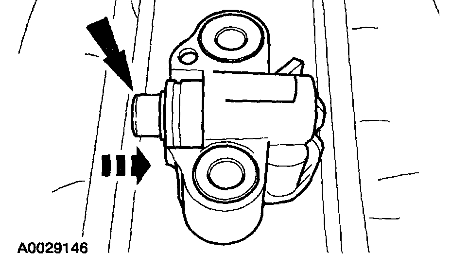
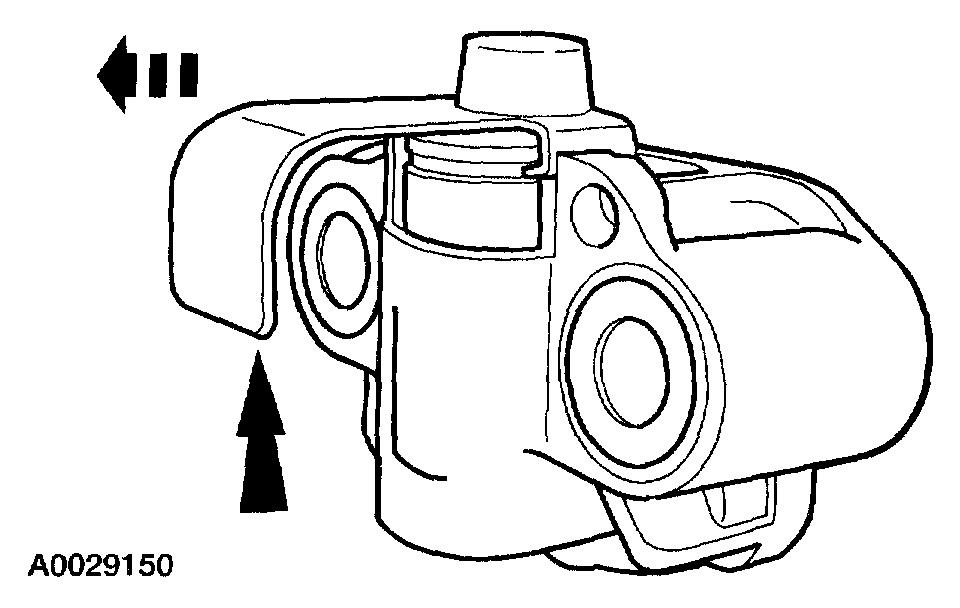
1. CAUTION: Timing chain procedures must be followed exactly or damage to valves and pistons will result.
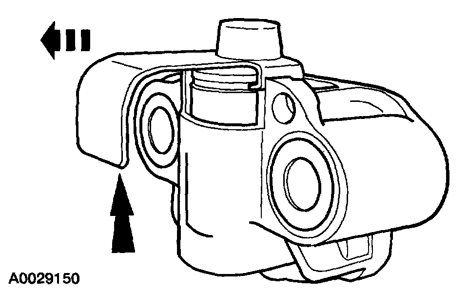
Compress the tensioner plunger, using a vise.
Pic 9
2. Install a retaining clip on the tensioner to hold the plunger in during installation.
3. Remove the tensioner from the vise.
Pic 10
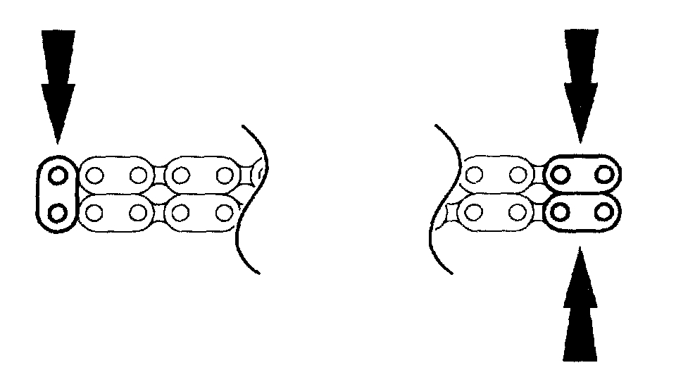
4. If the copper links are not visible mark two links on one end and one link on the other end, and use as timing marks.
Pic 11
5. Install the timing chain guides.
Pic 12
6. CAUTION: Do not turn the engine over with the Camshaft Alignment Set or damage to the camshaft sprocket or the bolt can occur.
Install the special tool.
Pic 13
7. NOTE: Slightly loosen the Camshaft Position Aligner tools to allow slight camshaft movement.
Pre-position the camshafts.
1 Rotate the LH camshaft with the Camshaft Alignment Set until the timing mark is approximately at 12 o'clock.
2 Rotate the RH camshaft with the Camshaft Alignment Set until the timing mark is approximately at 11 o'clock.
- Tighten the Camshaft Position Aligner tools to maintain camshaft pre-positioning.
Pic 14
8. CAUTION: Unless otherwise instructed, at no time when the timing chains are removed and the cylinder heads are installed is the crankshaft or camshaft to be rotated. Severe piston and valve damage will occur.
CAUTION: Rotate the crankshaft counterclockwise only. Do not rotate past position shown or severe piston and valve damage can occur.
NOTE: The number one cylinder is at Top Dead Center (TDC) when the stud on the engine block fits into the slot in the handle of the special tool.
Position the crankshaft so the number one cylinder is at TDC with the special tool.
9. Remove the Crankshaft Holding Tool.
Pic 15
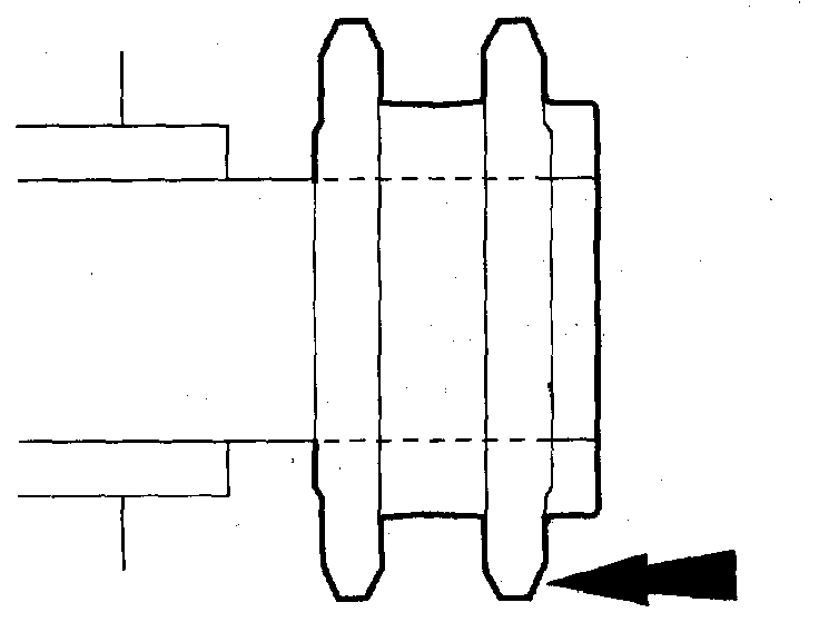
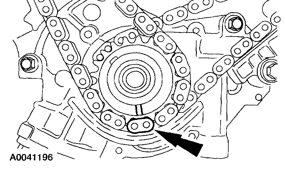
10. Install the crankshaft sprocket, making sure the flange faces forward.
Pic 16
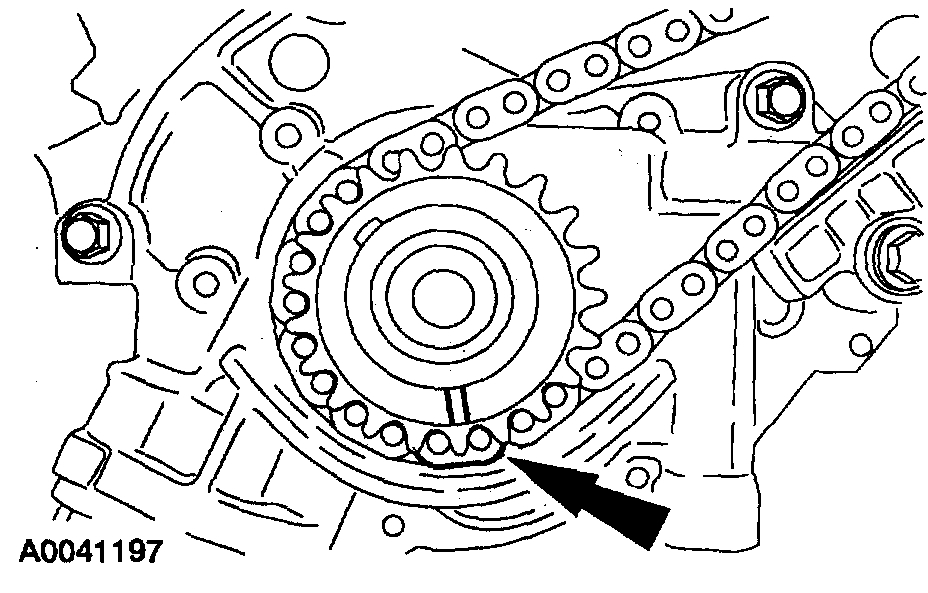
11. Position the lower end of the LH (inner) timing chain on the crankshaft sprocket, aligning the timing mark on the outer flange of the crankshaft sprocket with the single copper (marked) link on the chain.
Pic 17
12. NOTE: Make sure the upper half of the timing chain is below the tensioner arm dowel.
NOTE: If necessary, use the Camshaft Alignment Set to adjust the camshaft sprocket slightly to obtain timing mark alignment.
Position the timing chain on the camshaft sprocket with the camshaft sprocket timing mark positioned between the two copper (marked) chain links.
Pic 18
13. NOTE: The LH timing chain tensioner arm has a bump near the dowel hole, for identification.
Position the LH timing chain tensioner arm on the dowel pin and install the LH timing chain tensioner.
Pic 19
14. Remove the retaining clip from the LH timing chain tensioner.
Pic 20
15. NOTE: The lower half of the timing chain must be positioned above the tensioner arm dowel.
Position the lower end of the RH (outer) timing chain on the crankshaft sprocket, aligning the timing mark on the sprocket with the single copper (marked) link on the timing chain.
Pic 21
16. NOTE: If necessary, use the Camshaft Alignment Set to adjust the camshaft sprocket slightly to obtain timing mark alignment.
Position the RH timing chain on the camshaft sprocket. Make sure the camshaft sprocket timing mark is positioned between the two copper (marked) chain links.
Pic 22
17. Position the RH timing chain tensioner arm on the dowel pin and install the RH timing chain tensioner.
Pic 23
18. Remove the retaining clip from the RH timing chain tensioner.
Pic 24
19. Remove the special tool.
Pic 25
20. As a post-check, verify correct alignment of all timing marks.
Pic 26
21. Remove the special tool.
Pic 27
22. Position the crankshaft sensor ring on the crankshaft.
23. Install the engine front cover.
_________________________________________
Oil Pump
2003 Ford Truck F 150 2WD Pickup V8-5.4L Prop SOHC VIN Z
Procedures
Vehicle Engine, Cooling and Exhaust Engine Engine Lubrication Oil Pump Service and Repair Procedures
PROCEDURES
Oil Pump
Removal
1. Remove the timing chains.
2. Remove the oil pan.
Pic 28
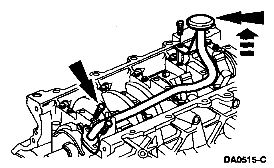
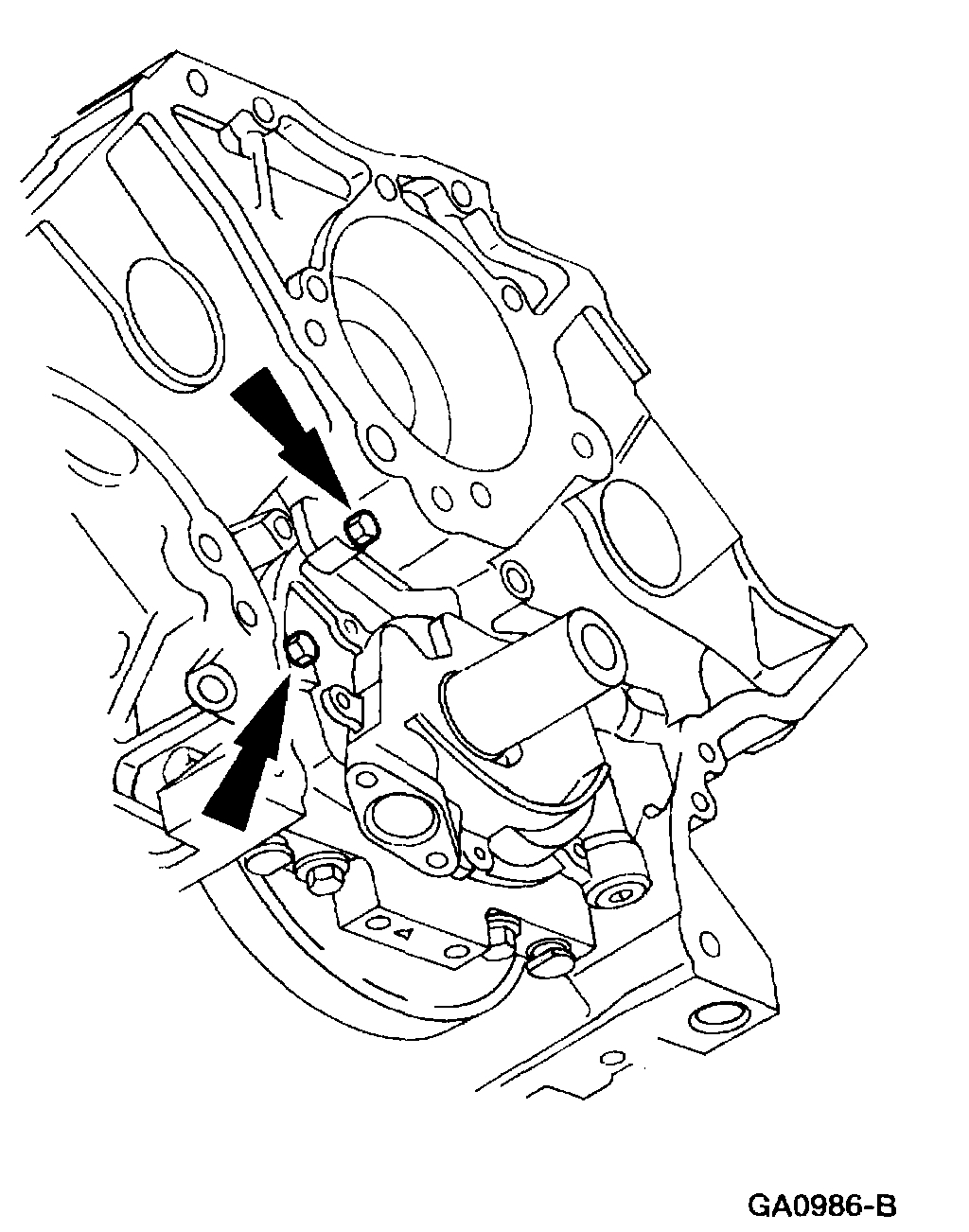
3. If necessary, remove the three bolts and the oil pump screen and pickup tube.
Pic 29
4. Remove the oil pump.
- Remove the three bolts.
- Remove the oil pump.
Installation
All vehicles
1. NOTE: Lubricate the new O-ring seal with clean engine oil.
Clean and inspect the mating surfaces and install a new O-ring seal.
Pic 30
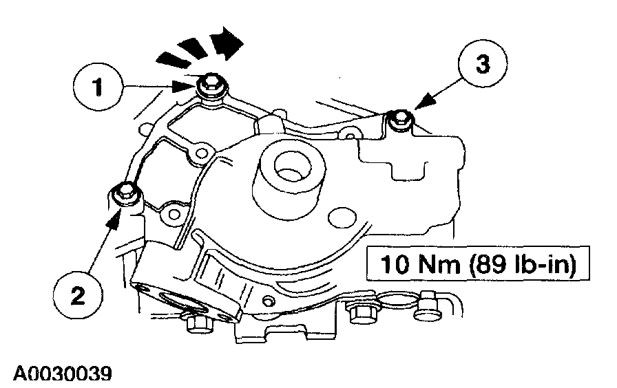
2. Install the oil pump and loosely install the bolts.
- Position the oil pump.
- Loosely install the bolts.
- Tighten the bolts in the sequence shown.
4x4 vehicles
pic 31
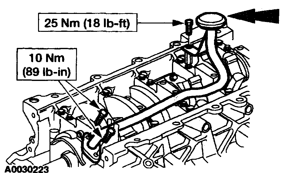
3. CAUTION: Make sure the O-ring is in place and not damaged. A missing or damaged O-ring can cause foam in the lubrication system, low oil pressure and severe engine damage.
NOTE: Install a new O-ring and lubricate with clean engine oil.
Install the oil pump screen and pickup tube bolts.
All vehicles
4. Install the timing chains.
5. CAUTION: The oil pump must be primed prior to starting the engine.
Install the oil pan.
______________________________________
I hope this helps. Let me know if you have other questions.
Take care and God Bless,
Joe
Images (Click to make bigger)
SPONSORED LINKS
Wednesday, February 3rd, 2021 AT 5:27 PM