Hello
Since you were unable to provide the codes. . .. . .. . ...I have attached tests per your request.
TEST B1 - VAT SENSOR
NOTE: Perform this test only when service code 24, 28, 54, 58, 64, or 68 is received in QUICK TEST. Ambient air temperature must be at least 50 °F (10 °C) for test results to be valid. Avoid performing test in unusually hot or cold conditions.
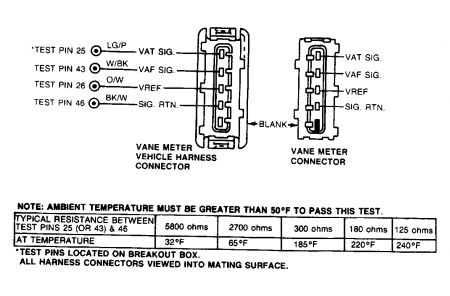
Fig. 13: VAT Sensor Circuit
VANE AIR TEMPERATURE (VAT) SENSOR SPECIFICATIONS
Temperature: °F ( °C) Volts K Ohms
50 (10) 3.46 3.77
68 (20) 3.07 2.50
86 (30) 2.65 1.70
104 (40) 2.23 1.18
122 (50) 1.84 0.83
140 (60) 1.49 0.60
158 (70) 1.19 0.44
176 (80) 0.95 0.33
194 (90) 0.76 0.25
212 (100) 0.56 0.19
230 (110) 0.46 0.14
248 (120) 0.38 0.11
1. Code 24 or 28: Check Ambient Temperature. Codes 24 and 28 indicate that the VAT sensor is out of Self-Test range. Correct range for measurement is .35-3.5 volts. Possible causes are; low ambient temperature, Faulty VAF meter, faulty ECA, faulty wiring or connector. Ensure ambient air temperature is at least 50 °F (10 °C). If not, repeat QUICK TEST. If temperature is at least 50 °F (10 °C), go to next step.
2. Check For VREF at TPS. Turn key off and wait 10 seconds. Disconnect TPS. Set DVOM on 20-volt scale. Turn key on, leaving engine off. Measure voltage at TPS harness connector between VREF and SIG RTN. If reading is not 4-6 volts, go to TEST A3 - REF . VOLTAGE, step 1). If voltage is 4-6 volts, connect TPS and go to next step.
3. Checking VAT Sensor. Ensure ambient temperature is greater than 50 °F. Turn key off and wait 10 seconds. Disconnect harness from vane meter. Set DVOM on 200K-ohm scale. Measure resistance at VAT sensor between VAT SIG and SIG RTN. See Fig. 13 . If resistance is 125 ohms at 240 °F (116 °C) to 3700 ohms at 50 °F (10 °C), replace ECA. Connect vane meter and repeat QUICK TEST. If reading is out of range, remove vane meter. Spray carburetor cleaner on a clean cloth and pass cloth through meter to remove oil film buildup. DO NOT spray inside vane meter. Reinstall vane meter. Repeat quick test. If code is still present, replace vane meter and repeat QUICK TEST.
4. Code 54 or 58: Induce Opposite Code. Code 54 and 58 indicate VAT sensor signal is greater than the Self-Test maximum of 3.5 volts (temperature is too low). Possible causes are a lack of continuity between the vane meter harness connector and ECA, a faulty vane meter, or a faulty ECA. Turn key off and wait 10 seconds. Disconnect harness from vane meter. Inspect and repair any damaged wiring. Install a jumper wire between VAT SIG and SIG RTN at vane meter harness connector. Perform KOEO SELF-TEST. If Code 64 or 68 is displayed, replace vane meter, remove jumper wire, reconnect vane meter, and repeat QUICK TEST. If code 64 or 68 is not displayed, remove jumper wire and go to next step.
5. Checking Continuity of VAT Signal and Signal Return. Turn key off and wait 10 seconds. Disconnect vane meter and keep jumper wire removed. Disconnect ECA 60-pin connector. Inspect for and repair any damaged wiring. Install breakout box, leaving ECA disconnected. Set DVOM on 200-ohm scale. Measure resistance between test pin No. 25, at the breakout box and VAT SIG at vane meter harness connector. Also measure resistance between test pin No. 46 and SIG RTN at vane meter harness connector. If both readings are less than 5 ohms, replace ECA. Remove breakout box and connect wiring to ECA and vane meter. Repeat QUICK TEST. If either reading is 5 ohms or more, repair open circuit. Remove breakout box, connect wiring to ECA and vane meter. Repeat QUICK TEST.
6. Code 64 or 68: Opposite Code Test. Service Code 64 or 68 indicates VAT sensor signal is less than Self-Test minimum value of 0.35 volts (Temperature is too High). Possible causes are, VAT signal output shorted to SIG RTN, ground, or VREF. A faulty vane meter or ECA. Turn key off and wait 10 seconds. Disconnect harness from vane meter. Inspect for and repair any damaged wiring. Perform KOEO SELF-TEST. If Code 54 or 58 is displayed, replace vane meter and reconnect harness. Repeat QUICK TEST. If Code 54 or 58 is not displayed, go to next step.
7. Checking VREF at TPS. Turn key off and wait 10 seconds. Disconnect TPS. Set DVOM on 20-volt scale. Turn key on, leaving engine off. Measure voltage between VREF and SIG RTN at TPS harness connector. If reading is not 4-6 volts, go to TEST A3 - REF . VOLTAGE, step 1). If reading is 4-6 volts, connect TPS and go to next step.
8. Checking VAT Signal For Shorts. Turn key off and wait 10 seconds. Disconnect vane meter. Disconnect ECA 60-pin connector. Inspect and repair as necessary. Install breakout box, with ECA disconnected. Set DVOM on 200K-ohm scale. Measure resistance between test pin No. 25 and test pins No. 40, 46, and 60 of breakout box. If any reading is less than 10K ohms, repair shorts in circuit(s). Remove breakout box, connect ECA and vane meter. Repeat QUICK TEST. If all readings are greater than 10K ohms, replace ECA. Remove breakout box and connect ECA. Repeat QUICK TEST.
9. Continuous Code 54 or 58: VAT Sensor Check. A Continuous Memory Code 54 or 58 indicates that the VAT signal was greater than the Self-Test maximum of 4.5 volts. The code was set during normal driving conditions. Possible causes are, faulty harness or connectors, ECA or vane meter. Enter KOEO CONTINUOUS MONITOR (WIGGLE) TEST. Observe VOM or diagnostic tester for indication of fault while lightly tapping vane meter and then by wiggling connector. If fault is indicated, inspect connector and terminals and repair or replace as necessary. If connector and terminals are good, replace vane meter and repeat QUICK TEST. If a fault is not indicated, go to next step.
10. EEC-IV Harness Check. While in CONTINUOUS MONITOR (WIGGLE) TEST, wiggle and bend EEC-IV harness from VAT sensor to instrument panel, a small section at a time. Also check harness from instrument panel to ECA. If fault is indicated, isolate fault and repair as necessary. Repeat QUICK TEST. If no fault is found, go to next step.
11. Checking ECA Harness and Connectors. Turn key off and wait 10 seconds. Disconnect ECA 60-pin connector. Inspect both connector and connector terminals for obvious damage. If connectors and terminals are damaged, repair or replace as necessary and repeat QUICK TEST. If connectors and terminals are okay, and you are unable to duplicate fault at this time, clear codes and repeat QUICK TEST.
12. Continuous Memory Codes 64 or 68: VAT Sensor Check. A Code 64 or 68 indicates VAT signal was less than Self-Test minimum of 0.3 volt. The code was set during normal driving conditions. Possible causes for this fault: faulty harness or connectors, ECA or VAF meter. Enter KOEO CONTINUOUS MONITOR (WIGGLE) TEST, observe VOM or diagnostic tester for indication of fault while tapping VAT sensor lightly and wiggling connector. If fault is indicated, inspect connector and terminals. If connector and terminals are good, replace vane meter and repeat QUICK TEST. If no fault is indicated, repeat steps 10) and 11).
TEST B2 - ACT SENSOR
NOTE: Perform this test when Service Code 24, 54, or 64 is displayed during QUICK TESTS or when directed here by other test procedures.
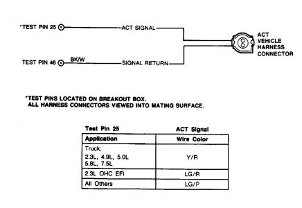
Fig. 14: Air Charge Temperature (ACT) Sensor Circuit
To prevent replacement of good components, be aware that the following non-EEC related areas may be at fault: cooling system, improper engine oil level, or air cleaner duct problems. Ambient air temperature must be at least 50 °F (10 °C) for test results to be valid. Avoid performing test in unusually hot or cold conditions.
AIR CHARGE TEMPERATURE (ACT) SENSOR SPECIFICATIONS
Temperature: °F ( °C) Volts K Ohms
50 (10) 3.51 58.75
68 (20) 3.07 37.30
86 (30) 2.60 24.27
104 (40) 2.13 16.15
122 (50) 1.70 10.97
140 (60) 1.33 7.70
158 (70) 1.02 5.37
176 (80) 0.78 3.84
194 (90) 0.60 2.80
212 (100) 0.46 2.07
230 (110) 0.35 1.55
248 (120) 0.27 1.18
1. Service Code 24: Checking ACT Sensor. Code 24 indicates that the ACT is out of the Self-Test limit range. Correct range for Self-Test measurement is 0.3-3.7 volts. Possible causes for this code are: ACT resistance out of limits or a faulty ECA. For vehicles with ACT sensor mounted in intake manifold, go to next step. If sensor is properly mounted in air cleaner on all other models, go to next step. If sensor is not properly mounted, install ACT sensor properly and repeat QUICK TEST.
2. Checking VREF at TPS. Turn key off and wait 10 seconds. Set DVOM on 20-volt scale and disconnect TPS. With KOEO, measure voltage between VREF and SIG RTN at TPS harness connector. If reading is less than 4 volts or more than 6 volts, go to TEST A3 - REF . VOLTAGE, step 1). If reading is between 4 and 6 volts, connect TPS and go to next step.
3. Checking ACT With Engine Off. Start engine and ensure engine reaches normal operating temperature. Turn key off and wait 10 seconds. Disconnect ACT sensor, set DVOM on 200K-ohm scale and measure ACT sensor resistance. If reading is less than 1100 ohms or more than 58K ohms, check function of heat stove duct valve. If valve is operating correctly, replace ACT sensor. Connect ACT sensor, and repeat QUICK TEST. If reading is between 1100 and 58K ohms, go to next step.
4. Checking ACT With Engine Running. Turn key off. Disconnect ACT sensor harness. Set DVOM on 200K-ohm scale and run engine for 2 minutes. While engine is running, measure ACT sensor resistance. If reading is between 2400 and 29K ohms, replace ECA. Connect ACT harness, and repeat QUICK TEST. If reading is less than 2400 ohms or more than 29,000 ohms, check function of heat stove duct valve. If valve works properly, replace ACT sensor. Repeat QUICK TEST.
5. Code 54: Generate Code 64. Code 54 indicates the ACT signal is greater than the Self-Test maximum value of 4.6 volts, which could also indicate an open circuit. Possible causes for this code are, open in harness wiring, faulty ACT sensor or faulty ECA. Turn key off and wait 10 seconds. Disconnect ACT sensor harness. Inspect for and repair any damaged wiring. Install a jumper wire between ACT SIGNAL and SIGNAL RETURN at connector. Perform KOEO SELF-TEST. If code 64 is displayed, replace ACT sensor. Remove jumper wire, connect ACT sensor, and repeat QUICK TEST. If code 64 is not displayed, remove jumper wire and go to next step.
6. Continuity Check of ACT Signal and Signal Return. Turn key off and wait 10 seconds. Leave ACT sensor harness disconnected. Disconnect ECA 60-pin connector. Inspect for and repair any damaged wiring. Install breakout box, leaving ECA disconnected. Set DVOM on 200-ohm scale. Measure resistance between test pin No. 25 and ACT SIGNAL at ACT connector, and between test pin No. 46 and SIGNAL RETURN at ACT connector. If both readings are less than 5 ohms, replace ECA and remove breakout box. Connect ECA and ACT sensor, and repeat QUICK TEST. If either reading is 5 ohms or more, repair opens in circuit. Remove breakout box, and connect ECA and ACT sensor. Repeat QUICK TEST.
7. Code 64: Generate Code 54. Code 64 indicates that the ACT signal is less than the Self-Test minimum value of 0.2 volt (grounded circuit). Possible cause for this fault are, faulty ACT sensor, short to ground in harness, faulty ECA. Turn key off and wait 10 seconds. Disconnect ACT sensor. Inspect for and repair any damaged wiring. Perform KOEO SELF-TEST. If code 54 is displayed, replace ACT sensor. Connect harness, and repeat QUICK TEST. If code 54 is not displayed, go to next step.
8. Checking VREF at TPS. Turn key off and wait 10 seconds. Set DVOM on 20-volt scale and disconnect TPS. Turn key on, leaving engine off. Measure voltage at TPS harness connector between VREF and SIGNAL RETURN at TPS connector (refer to wiring diagram for TEST B8 - TPS). If reading is less than 4 volts or more than 6 volts, go to TEST A3 - REF . VOLTAGE, step 1). If reading is between 4 and 6 volts, connect TPS and go to next step.
9. Checking ACT Signal for Ground Short. Turn key off and wait 10 seconds. Disconnect harness at ACT sensor. Disconnect ECA 60 pin connector. Inspect for and repair any damaged wiring. Install breakout box and set DVOM on 200K-ohm scale. Measure resistance between test pin No. 25 and test pins No. 40, 46, and 60. If any reading is less than 10K ohms, repair shorts. Remove breakout box, and connect ECA and ACT sensor. Repeat QUICK TEST. If all readings are 10K ohms or more, replace ECA. Remove breakout box, and connect ECA and ACT sensor. Repeat QUICK TEST.
10. Continuous Memory Code 54: Check ACT Sensor. Code 54 indicates that the ACT signal was greater then the Self-Test maximum value sometime during vehicle operation. Possible causes for this fault are; faulty ACT sensor, open in harness or faulty ECA. Using KOEO CONTINUOUS MONITOR (WIGGLE) TEST, observe VOM or diagnostic tester for indication of fault while tapping ACT sensor lightly and wiggling connector. If fault is indicated, inspect connector and terminals. If connector and terminals are good, replace ACT sensor and repeat QUICK TEST. If no fault is indicated, go to next step.
11. Wiggle Testing ACT Harness. While in CONTINUOUS MONITOR (WIGGLE) TEST, wiggle and bend small sections of harness from ACT sensor to firewall. Repeat action from firewall to ECA. If fault is indicated, isolate fault and repair as necessary. Clear continuous memory codes and repeat QUICK TEST. If no fault is indicated, go to next step.
12. Inspecting Connectors and Terminals. Turn key off and wait 10 seconds. Disconnect ECA 60-pin connector. Inspect both connector and connector terminals for obvious damage. If connectors and terminals are not okay, repair as necessary, clear continuous memory code and repeat QUICK TEST. If connectors and terminals are okay, and you are unable to duplicate fault at this time, clear continuous memory and repeat QUICK TEST.
13. Continuous Memory Code 64: Check ACT Sensor. Code 64 indicates that the ACT sensor signal was less than the Self-Test minimum value of 0.2 volt sometime during vehicle operation. Possible causes of this fault are; faulty ACT sensor, open in harness or faulty ECA. Using KOEO CONTINUOUS MONITOR (WIGGLE) TEST, observe VOM or diagnostic tester for indication of fault while tapping ACT sensor lightly and wiggling connector. If fault is indicated, inspect connector and terminals. If connector and terminals are good, replace ACT sensor and repeat QUICK TEST. If no fault is indicated, repeat step 11).
TEST B5 - ECT SENSOR
NOTE: Perform this test when directed to by a Code 21, 51, or 61 during QUICK TEST procedure. For purposes of this test, a "WARMED UP" engine has a coolant temperature of 50-240 °F (10-116 °C) for KOEO SELF-TEST and 180-240 °F (82-116 °C) for KOER SELF-TEST. The test procedure will be invalid outside these ranges.
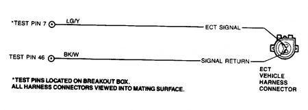
Fig. 17: Engine Coolant Temperature (ECT) Sensor Circuit
ECT SENSOR SPECIFICATIONS
Temperature: °F ( °C) Voltage Resistance: K-Ohms
248 (120) .27 1.18
230 (110) .35 1.55
212 (100) .46 2.07
194 (90) .60 2.80
176 (80) .78 3.84
158 (70) 1.02 5.37
140 (60) 1.33 7.70
122 (50) 1.70 10.97
104 (40) 2.13 16.15
86 (30) 2.60 24.27
68 (20) 3.07 37.30
50 (10) 3.51 58.75
To prevent replacement of good components, be aware that the following non-EEC related areas may be at fault: coolant or oil level, blocked or obstructed airflow, engine not at normal operating temperature, or cooling fan.
1. Service Code 21: Check Engine Operating Temperature. Code 21 indicates that the ECT is out of the 0.3-3.5 volt Self-Test range. Possible causes are: ECT resistance out of limits or faulty ECA. If engine will not start, go to step 4). Start engine and run at 2000 RPM for 2 minutes. Check that upper radiator hose is hot and pressurized. Repeat QUICK TEST before continuing. If vehicle stalls, DO NOT service code 21 at this time, go to TEST D19 - SYSTEM CHECK . If code 21 is not displayed, service other codes as necessary. If code 21 appears, go to next step.
2. Checking for VREF at TPS. Turn key off and wait 10 seconds. Disconnect TPS. Set DVOM on 20-volt scale. With KOEO measure voltage at TPS harness connector between VREF and SIG RTN. See Fig. 17 . If voltage is not 4-6 volts, go to TEST A3 - REF . VOLTAGE, step 1). If voltage is 4-6 volts, reconnect TPS and go to next step.
3. ECT Sensor Resistance. Ensure engine is fully warmed up for this step. Turn key off and wait 10 seconds. Disconnect wiring harness at ECT sensor. See Fig. 17 . Set DVOM on 200K-ohm scale and measure resistance of ECT sensor. If reading is 1300 ohms (240 °F) to 7700 ohms (140 °F) with engine off and 1550 ohms (230 °F) to 4550 ohms (170 °F) with engine running, replace ECA. Reconnect ECT sensor and repeat QUICK TEST. If readings are not as specified, replace ECT sensor, connect harness, and repeat QUICK TEST.
4. Checking ECT Sensor Resistance With A No Start Condition. With key off, disconnect ECT sensor and set DVOM on 200K-ohm scale. Measure resistance of ECT sensor and compare with above ECT SENSOR SPECIFICATIONS table. If resistance is within specifications, DO NOT service Code 21 at this time. Go to TEST A1 - NO START . If resistance is not within specification, replace ECT sensor, connect ECT sensor and repeat quick test.
5. Service Code 51: Attempt To Generate Code 61. Code 51 indicates that the ECT signal is greater than the Self-Test maximum value of 4.6 volts (open circuit). Possible causes are: faulty ECT sensor, open circuit or faulty ECA. Turn key off and wait 10 seconds. Disconnect wiring harness from ECT sensor. Inspect and repair wiring as necessary. Connect a jumper wire between ECT SIGNAL and SIGNAL RETURN terminals of ECT harness connector. See Fig. 17 . Perform KOEO SELF-TEST. If Code 61 is displayed, replace ECT sensor, remove jumper wire, reconnect ECT sensor and repeat QUICK TEST. If Code 61 is not displayed, remove jumper wire and go to next step.
6. ECT Signal and Signal Return Continuity Check. Turn key off and wait 10 seconds. Disconnect harness from ECT sensor. Disconnect ECA 60-pin connector. Inspect and repair any damaged wiring. Install breakout box, leaving ECA disconnected. Set DVOM on 200-ohm scale. Measure resistance between ECT SIGNAL at ECT harness connector and test pin No. 7 at breakout box. Measure resistance between SIGNAL RETURN at ECT harness connector and test pin No. 46 at breakout box. If both readings are less than 5 ohms, replace ECA, remove breakout box, reconnect components and repeat QUICK TEST. If either reading is not less than 5 ohms, repair open circuit(s). Remove breakout box, and connect ECA and ECT sensor. Repeat QUICK TEST.
7. Service Code 61: Attempt To Generate Code 51. Code 61 indicates that the ECT signal is less than the 0.2 volt Self-Test minimum value (grounded circuit). Possible causes are: faulty ECT, grounded circuit or faulty ECA. Turn key off and wait 10 seconds. Disconnect ECT sensor. Inspect and repair connector and/or wiring as necessary. Perform KOEO SELF-TEST. If Code 51 is displayed, replace ECT sensor, connect sensor, and repeat QUICK TEST. If Code 51 is not displayed, go to next step.
8. Checking For VREF at TPS. Turn key off and wait 10 seconds. Set DVOM on 20-volt scale. Disconnect TPS. Turn key on, leaving engine off. Measure voltage between VREF and SIGNAL RETURN at TPS harness connector. See Fig. 20 . If reading is not 4-6 volts, go to TEST A3 - REF . VOLTAGE, step 1). If reading is 4-6 volts, reconnect TPS and go to next step.
9. Checking ECT Signal for Short to Ground. Turn key off and wait 10 seconds. Disconnect harness from ECT sensor. Disconnect ECA 60-pin connector. Inspect and repair any damaged wiring. Install breakout box, leaving ECA disconnected. Set DVOM on 200K-ohm scale. Measure resistance between test pin No. 7 and test pins No. 40, 46, and 60 at breakout box. If any reading is less than 10K ohms, repair short circuits. Remove breakout box, connect ECA and ECT sensor, and repeat QUICK TEST. If all readings are 10K ohms or more, replace ECA. Remove breakout box, connect ECA and ECT sensor and repeat QUICK TEST.
10. Continuous Memory Code 51: Check ECT Sensor. Code 51 indicates that the ECT signal was greater than the Self-Test maximum voltage of 4.6 volts sometime during vehicle operation. Possible causes are: faulty ECT sensor, open harness or faulty ECA. Enter KOEO CONTINUOUS MONITOR (WIGGLE) TEST. Observe VOM or diagnostic tester for indication of fault while tapping ECT sensor and wiggling ECT connector. If fault is indicated, disconnect and inspect ECT connector and terminals. If connector and terminals are okay, replace ECT sensor, clear continuous memory and repeat QUICK TEST. If no fault is indicated, go to next step.
11. Checking EEC-IV Harness. While in KOEO CONTINUOUS MONITOR (WIGGLE) TEST, observe VOM or diagnostic tester for indication of fault as you bend, shake or wiggle EEC-IV harness. Start at sensor connector and work toward dash panel. Also test harness from dash panel to ECA in same manner. If fault is indicated, isolate fault in wiring and repair as necessary. Clear continuous memory and repeat QUICK TEST. If fault is not indicated, go to next step.
12. Checking ECA and Harness Connectors. Turn key off and wait 10 seconds. Disconnect ECA 60-pin connector. Inspect both connectors and terminals for damage and repair as necessary. Repeat QUICK TEST. If connectors and terminals are okay, fault cannot be duplicated at this time. Go to next step.
13. Continuous Memory Code 61: Check ECT Sensor. Code 61 indicates that the ECT signal was less than the 0.2 volt Self-Test minimum value (grounded circuit) sometime during vehicle operation. Possible causes are: faulty ECT, grounded circuit or faulty ECA. Using KOEO CONTINUOUS MONITOR (WIGGLE) TEST, observe VOM or diagnostic tester for indication of fault while tapping ECT sensor and wiggling ECT connector. If fault is indicated, disconnect and inspect ECT connector and terminals. If connector and terminals are okay, replace ECT sensor and repeat QUICK TEST. If no fault is indicated, repeat step 11).
Thursday, February 26th, 2009 AT 10:18 PM