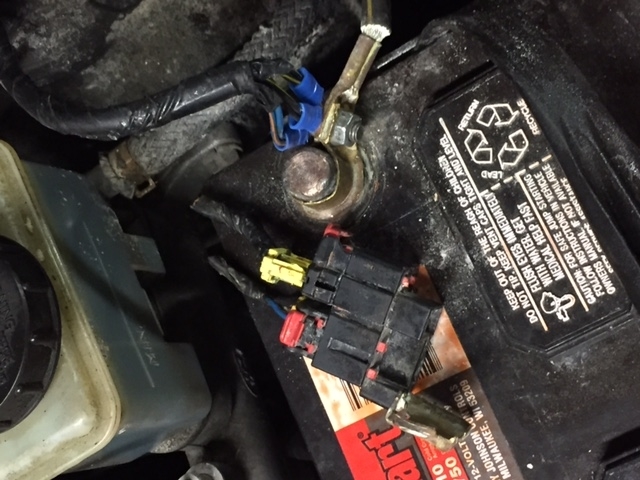
I found this. Not sure it will help. Have not been able to find volts for the VSS at the cluster, but shows Ohms in tests below.
TEST D: SPEEDOMETER/ODOMETER INACCURATE
Coupe
1.Turn ignition off. Connect scan tool and retrieve Diagnostic Trouble Codes (DTC) following manufacturer's instructions. If no DTCs are present, go to next step. If DTCs are present, see appropriate SELF-DIAGNOSTICS article in ENGINE PERFORMANCE. Repair DTCs as necessary, then retest system.
2.Using scan tool, observe Vehicle Speed Sensor (VSS) output Parameter Identification (PID) while assistant drives vehicle over range of speeds on various road surfaces. If VSS PID varies smoothly with vehicle speed, go to next step. If VSS PID does not vary or is erratic, see appropriate SELF-DIAGNOSTICS article in ENGINE PERFORMANCE to diagnose VSS.
3.Remove and check OBDII 10-amp fuse in engine compartment fuse box. If fuse is okay, reinstall fuse and go to step 5 . If fuse is blown, go to next step.
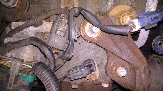
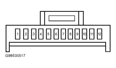
4.Turn ignition off. Remove instrument cluster. See INSTRUMENT CLUSTER under REMOVAL & INSTALLATION. Disconnect all instrument cluster electrical connectors. Measure resistance between ground and instrument cluster harness connector C253 terminal No. 1 (Green wire). See Fig. 7 . Resistance should be more than 10 k/ohms. If resistance is more than 10 k/ohms, replace OBDII 10-amp fuse and go to next step. If resistance is less than 10 k/ohms, repair short to ground Green wire between instrument cluster harness connector and fuse. See WIRING DIAGRAMS .
5.Turn ignition off. Remove instrument cluster. See INSTRUMENT CLUSTER under REMOVAL & INSTALLATION. Disconnect instrument cluster electrical connectors. Measure voltage between ground and instrument cluster harness connector C253 terminal No. 1 (Green wire). See Fig. 7 . Voltage should be more than 10 volts. If voltage is more than 10 volts, go to next step. If voltage is less than 10 volts, repair short to voltage in Green wire between instrument cluster harness connector and fuse. See WIRING DIAGRAMS .
6.Turn ignition off. Disconnect Vehicle Speed Sensor (VSS) harness connector C132. Measure resistance of Blue wire between VSS harness connector and instrument cluster harness connector C252 terminal No. 11. See Fig. 6 . Measure resistance of White/Black wire between VSS harness connector C132 and instrument cluster harness connector C252 terminal No. 1. Resistance in both tests should be less than 5 ohms. If resistances are as specified, go to next step. If resistances are not as specified, repair open in White/Black or Blue wire. See WIRING DIAGRAMS .
7.Measure resistance between ground and instrument cluster harness connector C252 terminal No. 1 (White/Black wire). Measured resistance should be more than 10 k/ohms. If resistance is more than 10 k/ohms, go to next step. If resistance is less than 10 k/ohms, repair short to ground in White/Black wire.
8.Turn ignition on. Measure voltage between ground and instrument cluster harness connector C252 terminal No. 12 (Black/Yellow wire). See Fig. 6 . Voltage should be more than 10 volts. If voltage is more than 10 volts, go to next step. If voltage is less than 10 volts, repair short to voltage in Black/Yellow wire between instrument cluster connector and fuse. See WIRING DIAGRAMS .
9.Turn ignition off. Visually inspect instrument cluster printed circuit for damage, cracks or hot spots. If instrument cluster printed circuit is okay, replace speedometer. If instrument cluster printed circuit is damaged, replace printed circuit and gauge contact clips.
Sedan & Wagon
1.Turn ignition off. Connect scan tool and retrieve Diagnostic Trouble Codes (DTC) following manufacturer's instructions. If no DTCs are present, go to next step. If DTCs are present, see appropriate SELF-DIAGNOSTICS article in ENGINE PERFORMANCE. Repair DTCs as necessary, then retest system.
2.Using scan tool, observe Vehicle Speed Sensor (VSS) output Parameter Identification (PID) while assistant drives vehicle over range of speeds on various road surfaces. If VSS PID varies smoothly with vehicle speed, go to next step. If VSS PID does not vary or is erratic, see appropriate SELF-DIAGNOSTICS article in ENGINE PERFORMANCE to diagnose VSS.
3.Remove and check OBDII 10-amp fuse in engine compartment fuse box. If fuse is okay, reinstall fuse and go to step 5 . If fuse is blown, go to next step.
4.Turn ignition off. Remove instrument cluster. See INSTRUMENT CLUSTER under REMOVAL & INSTALLATION. Disconnect all instrument cluster electrical connectors. Measure resistance between ground and instrument cluster harness connector C252 terminal No. 12 (Green wire). See Fig. 6 . Measured resistance should be more than 10 k/ohms. If resistance is more than 10 k/ohms, replace OBDII 10-amp fuse and go to next step. If resistance is less than 10 k/ohms, repair short to ground in Green wire between instrument cluster harness connector and fuse. See WIRING DIAGRAMS .
5.Turn ignition off. Remove instrument cluster. See INSTRUMENT CLUSTER under REMOVAL & INSTALLATION. Disconnect instrument cluster electrical connectors. Measure voltage between ground and instrument cluster harness connector C252 terminal No. 12 (Green wire). See Fig. 6 . Voltage should be more than 10 volts. If voltage is more than 10 volts, go to next step. If voltage is less than 10 volts, repair short to voltage in Green wire between instrument cluster harness connector and fuse. See WIRING DIAGRAMS .
6.Turn ignition off. Disconnect Vehicle Speed Sensor (VSS) harness connector C132. Measure resistance of Blue wire between VSS harness connector and instrument cluster harness connector C252 terminal No. 7. See Fig. 6 . Measure resistance of White/Black wire between VSS harness connector C132 and instrument cluster harness connector C253 terminal No. 9. Resistance in both tests should be less than 5 ohms. If resistances are as specified, go to next step. If resistances are not as specified, repair open in White/Black or Blue wire. See WIRING DIAGRAMS .
7.Measure resistance between ground and instrument cluster harness connector C253 terminal No. 9 (White/Black wire). Resistance should be more than 10 k/ohms. If measured resistance is more than 10 k/ohms, go to next step. If resistance is less than 10 k/ohms, repair short to ground in White/Black wire.
8.Turn ignition on. Measure voltage between ground and instrument cluster harness connector C252 terminals No. 8 and 4 (Black/Yellow wire). See Fig. 6 . Voltage should be more than 10 volts. If voltage is more than 10 volts, go to next step. If voltage is less than 10 volts, repair short to voltage in Black/Yellow wire between instrument cluster connector and fuse. See WIRING DIAGRAMS .
9.Turn ignition off. Visually inspect instrument cluster printed circuit for damage, cracks or hot spots. If instrument cluster printed circuit is okay, replace speedometer. If instrument cluster printed circuit is damaged, replace printed circuit and gauge contact clips.
Fig 6
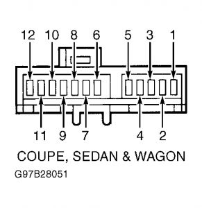
Fig 7
.
Sunday, July 26th, 2020 AT 10:55 AM
(Merged)