Engine replacement instructions please?

Tiny
DANIEL470
  • MEMBER
  • 14 POSTS
  • 1997 FORD F-150
Engine Mechanical problem
1997 Ford F150 V8 Four Wheel Drive Automatic

i am changing out a 97 4.6 romeo motor in a f-150. I am replacing with a 99 4.6 romeo motor. I've pretty much stripped the old motor but cant get to the top two tranny-engine bolts. Is there any way to get them out without pulling the cab or intake manifold?
Was this
answer
helpful?
Yes
No
Tuesday, February 9th, 2021 AT 2:27 PM (Merged)
Tiny
BLACKOP555
  • MECHANIC
  • 10,371 POSTS
Remove engine supporting crossmeber and tranny crossmemember and drop the engine and trans.
Was this
answer
helpful?
Yes
No
Tuesday, February 9th, 2021 AT 2:27 PM (Merged)
Tiny
RACEFAN966
  • MECHANIC
  • 5,029 POSTS
You will need to pull the intake to get to those. There is just no room. Check that engine closely as the Romeo engine has head problems from the factory.
Was this
answer
helpful?
Yes
No
Tuesday, February 9th, 2021 AT 2:27 PM (Merged)
Tiny
MIAMIII13
  • MEMBER
  • 40 POSTS
U will need to drop engine and tranny or yes u must take plentum off. Not that bad though. About an hours work if that.
Was this
answer
helpful?
Yes
No
Tuesday, February 9th, 2021 AT 2:27 PM (Merged)
Tiny
JEFFCORN1992
  • MEMBER
  • 8 POSTS
  • 1996 FORD F-150
  • 188,000 MILES
Hey I have a 1996 ford f150 4x4 with the 5.0 was wondering if a 5.0 out of a 89 f150 would bolt straight in? Thanks is it a straight swap?
Was this
answer
helpful?
Yes
No
Tuesday, February 9th, 2021 AT 2:27 PM (Merged)
Tiny
HMAC300
  • MECHANIC
  • 48,601 POSTS
Unless they have changed the way the motor mounts in the truck meanign where the current mounts go in it should be although you will have to put the more modern equiptment onit so it will be a bolt in swap. Meaning the intake/exaust, maybe oil pan and alternator, etc. Make sur ethe intake pattern bolts are the same as they may have changed like going to a smaller bolt or metric.
Was this
answer
helpful?
Yes
No
Tuesday, February 9th, 2021 AT 2:27 PM (Merged)
Tiny
JEFFCORN1992
  • MEMBER
  • 8 POSTS
Oh well I also have a seven inch lift will that matter?
Was this
answer
helpful?
Yes
No
Tuesday, February 9th, 2021 AT 2:27 PM (Merged)
Tiny
GRASSLARRY
  • MEMBER
  • 15 POSTS
  • 1993 FORD F-150
  • 5.0L
  • V8
  • 4WD
  • MANUAL
  • 200,000 MILES
I need to change the engine in my truck can you help me?
Was this
answer
helpful?
Yes
No
Tuesday, February 9th, 2021 AT 2:27 PM (Merged)
Tiny
JACOBANDNICKOLAS
  • MECHANIC
  • 108,269 POSTS
Hi,

I'm not sure I understand what you are asking. If it if it will work, yes, but you will need to switch everything from the 1990 on to the new engine. The components are different but the engine itself should work.

Let me know if that is what you needed.
Was this
answer
helpful?
Yes
No
+1
Tuesday, February 9th, 2021 AT 2:27 PM (Merged)
Tiny
GRASSLARRY
  • MEMBER
  • 15 POSTS
My 1993 needs engine. Have a 1990 engine. What do I need to change?
Was this
answer
helpful?
Yes
No
Tuesday, February 9th, 2021 AT 2:27 PM (Merged)
Tiny
GRASSLARRY
  • MEMBER
  • 15 POSTS
Will I need to change distributor?
Was this
answer
helpful?
Yes
No
Tuesday, February 9th, 2021 AT 2:27 PM (Merged)
Tiny
JACOBANDNICKOLAS
  • MECHANIC
  • 108,269 POSTS
I would recommend it. You want the ignition system working the same as it did. Here are directions for removal and replacement:

_________________
1993 Ford Truck F 150 2WD Pickup V8-302 5.0L
Distributor Assembly
Vehicle Powertrain Management Ignition System Distributor Service and Repair Procedures Removal and Installation Distributor Assembly
DISTRIBUTOR ASSEMBLY
Removal

1. Disconnect distributor from wiring harness.
2. Mark position of No. 1 cylinder wire tower on distributor base for reference when installing distributor.
3. Loosen distributor cap hold-down screws. Lift cap straight off distributor to prevent damage to rotor blade and spring. Position cap and attached wires aside so as not to interfere with distributor removal.
4. Remove rotor by pulling upward to remove it from the distributor shaft and armature.
5. Remove distributor hold-down bolt and clamp. Remove distributor by pulling upward.
6. Cover distributor opening in the cylinder block or head with a clean shop towel to prevent the entry of foreign material or dirt into the engine.

Installation

1. Visually inspect distributor.
2. Inspect O-ring. It should fit tightly and be free of cuts.
3. The drive gear should be free of nicks, cracks and excessive wear.
4. Rotate distributor shaft. It should move freely, without binding.
5. Remove No. 1 cylinder spark plug and rotate engine clockwise until No. 1 piston is on the compression stroke.
6. With No. 1 piston on compression stroke, align timing pointer with TDC on the crankshaft damper.

NOTE: To install distributor correctly, No. 1 piston must be at Top Dead Center (TDC) of compression stroke.

7. Align locating boss on rotor with hole on armature. Fully seat rotor on distributor shaft.
8. Rotate distributor shaft so blade on rotor is pointing toward mark on distributor base that was previously made.
9. While installing distributor, continue rotating rotor slightly so leading edge of the vane is centered in vane switch stator assembly.
10. Rotate distributor in block to align leading edge of vane and vane switch stator assembly. Verify rotor is pointing at No. 1 mark on distributor base.

NOTE: If vane and vane switch stator cannot be aligned by rotating distributor in cylinder block, remove distributor enough to disengage distributor gear from camshaft gear. Rotate rotor enough to engage distributor gear on another tooth of camshaft gear. Repeat Step 1 if necessary.

11. Install distributor hold-down clamp and bolt. Tighten bolt, but leave it loose enough to rotate distributor.
12. Install distributor cap, No. 1 spark plug and ignition wires. Check that ignition wires are securely connected to the cap and spark plugs. Tighten distributor cap hold-down screws to 2.0-2.6 Nm (18-23 in-lb).
13. Reconnect distributor to wiring harness.
14. Set initial timing.
15. After timing is set, tighten distributor hold-down bolt to 23-34 Nm (17-25 ft-lb).
6. Recheck initial timing. Adjust if necessary.

_________________________

Let me know if I can help.

Take care,
Joe
Was this
answer
helpful?
Yes
No
+1
Tuesday, February 9th, 2021 AT 2:27 PM (Merged)
Tiny
GRASSLARRY
  • MEMBER
  • 15 POSTS
What is firing order on 93 5.O? Is it same as 90 5.O?
Was this
answer
helpful?
Yes
No
Tuesday, February 9th, 2021 AT 2:27 PM (Merged)
Tiny
JACOBANDNICKOLAS
  • MECHANIC
  • 108,269 POSTS
Yep, they are the same. I attached a couple pics. Hope they help.

Joe
Was this
answer
helpful?
Yes
No
+1
Tuesday, February 9th, 2021 AT 2:27 PM (Merged)
Tiny
GRASSLARRY
  • MEMBER
  • 15 POSTS
What size is torx bit on intake?
Was this
answer
helpful?
Yes
No
Tuesday, February 9th, 2021 AT 2:27 PM (Merged)
Tiny
JACOBANDNICKOLAS
  • MECHANIC
  • 108,269 POSTS
Hi,

That is one I don't know off the top of my head. The manual doesn't provide that info, but usually those are around a T35.

___________________________

I don't know if you need them, but here are the directions for the 93 upper and lower intake removal and replacement. It includes torque specs. The attached pics correlate with the directions.

__________________________

1993 Ford Truck F 150 2WD Pickup V8-302 5.0L
Upper
Vehicle Engine, Cooling and Exhaust Engine Intake Manifold Service and Repair Procedures Upper
UPPER
WARNING: DO NOT SMOKE, CARRY LIGHTED TOBACCO OR OPEN FLAME OF ANY TYPE WHEN WORKING ON OR NEAR ANY FUEL-RELATED COMPONENT, HIGHLY FLAMMABLE MIXTURES ARE ALWAYS PRESENT AND MAY BE IGNITED, RESULTING IN POSSIBLE PERSONAL INJURY.

Upper Intake Manifold and Throttle Body

Removal

1. Disconnect electrical connectors at idle air control valve, throttle position sensor and EGR position sensor.
2. Disconnect throttle linkage at throttle ball. Disconnect AOD (5.0L only) or C6 (5.8L only) transmission linkage from throttle body. Remove two bolts securing throttle linkage bracket to intake. Position bracket with cables out of way.

CAUTION: When disconnecting throttle cable from ball stud, use a screwdriver or similar tool close to the stud and pry slowly. Pulling by hand may damage the cable.

3. Disconnect upper intake manifold vacuum fitting connections by disconnecting all vacuum lines to vacuum tree, vacuum lines to EGR valve and vacuum line to fuel pressure regulator.
4. Disconnect PCV system by disconnecting hose from fitting on rear of upper manifold.
5. On Econoline models, remove the oil fill tube.
6. Remove canister purge line(s) from fitting(s) on throttle body.
7. Disconnect water heater lines from the throttle body.
8. Disconnect EGR tube from EGR valve by removing flange nut.
9. Remove bolt from upper intake support bracket to upper manifold.
10. Remove six upper intake manifold retaining bolts.
11. Remove upper intake and throttle body as an assembly from lower intake manifold.

Installation

1. Clean and inspect the mounting faces of the lower and upper intake manifolds.
2. Position new gasket on lower intake mounting face. The use of alignment studs may be helpful.
3. Install upper intake manifold and throttle body assembly to lower manifold making sure gasket remains in place (if alignment studs are not used).
4. Install six upper intake manifold retaining bolts and tighten to 17-24 Nm (12-18 ft-lb).
5. Install upper intake support bracket to upper manifold attaching bolt.
6. Install EGR tube. Tighten flange nuts to 34-47 Nm (25-35 ft-lb).
7. Install canister purge lines to fittings on throttle body.
8. Connect water heater lines to the throttle body.
9. Connect PCV hose to rear of upper manifold.
10. Install oil fill tube (Econoline models).
11. Connect vacuum lines to vacuum tree, EGR valve and fuel pressure regulator.
12. Position throttle linkage bracket with cables to upper intake manifold. Install two retaining bolts and tighten to 11-13 Nm (8-10 ft-lb). Connect throttle cable and transmission cable to throttle body.
13. Connect electrical connectors at idle air control valve, TP sensor and EGR position sensor.
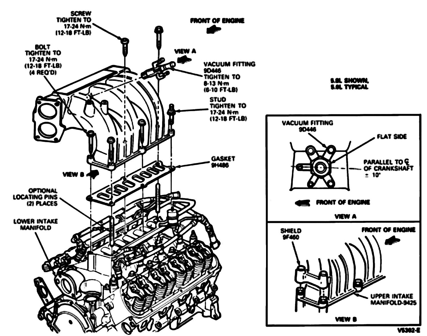
Pic 1

_____________________________________

1993 Ford Truck F 150 2WD Pickup V8-302 5.0L
Lower
Vehicle Engine, Cooling and Exhaust Engine Intake Manifold Service and Repair Procedures Lower
LOWER
1. Drain cooling system, then remove air cleaner with intake duct assembly and crankcase ventilation hose.
2. Disconnect accelerator cable and speed control linkage (if equipped) from carburetor or throttle body. Remove accelerator cable bracket, then disconnect kickdown rod from carburetor or throttle body on models equipped with automatic transmission. Disconnect electric choke, carburetor solenoid electrical connectors or EEC connector, if equipped.
3. Disconnect high tension lead and wires from ignition coil.
4. Disconnect ignition wires from spark plugs, then remove wires and bracket assembly from rocker arm cover attaching stud.
5. Remove distributor cap and ignition wires as an assembly.
6. Disconnect fuel inlet line from carburetor or throttle body.
7. Disconnect vacuum hoses from distributor, then remove distributor and disconnect evaporative hoses, if equipped.
8. Disconnect upper radiator hose from coolant outlet housing.
9. Disconnect electrical connector from coolant temperature sending unit, then remove heater hose from intake manifold.
10. Remove water pump bypass hose from coolant outlet housing, then disconnect crankcase vent hose from rocker arm cover.
11. Remove intake manifold attaching bolts, then the intake manifold and carburetor as an assembly. On models with EFI remove manifold as follows:
a. Remove upper intake manifold and throttle body as an assembly.
B. Remove lower intake manifold assembly.
C. It may be necessary to carefully pry the intake manifold from the cylinder heads. Remove manifold gaskets and seals and discard intake manifold attaching bolt sealing washer.

Fig. 13 Intake manifold installation

Pic 2

Fig. 14 Intake manifold bolt tightening sequence

pic 3

12. Reverse procedure to install. Apply sealer as shown in Fig. 13. Tighten manifold attaching bolts to specifications in sequence shown in Fig. 14.

_________________________

Hope that helps. Let me know if you have other questions.

Joe
Was this
answer
helpful?
Yes
No
+1
Tuesday, February 9th, 2021 AT 2:27 PM (Merged)
Tiny
GRASSLARRY
  • MEMBER
  • 15 POSTS
Can I disconnect smog pump and her valve?
Was this
answer
helpful?
Yes
No
Tuesday, February 9th, 2021 AT 2:27 PM (Merged)
Tiny
GRASSLARRY
  • MEMBER
  • 15 POSTS
EGR valve.
Was this
answer
helpful?
Yes
No
Tuesday, February 9th, 2021 AT 2:27 PM (Merged)
Tiny
JACOBANDNICKOLAS
  • MECHANIC
  • 108,269 POSTS
I'm not sure what you are asking. Both engine should have an EGR, correct? And the air / smog pump is needed to complete unburned exhaust gases.

Let me know. Sorry, not being there makes it a bit more tricky.

Joe
Was this
answer
helpful?
Yes
No
Tuesday, February 9th, 2021 AT 2:27 PM (Merged)
Tiny
GRASSLARRY
  • MEMBER
  • 15 POSTS
My 90 model engine didn't have smog pump.
Was this
answer
helpful?
Yes
No
Tuesday, February 9th, 2021 AT 2:27 PM (Merged)

Please login or register to post a reply.

Sponsored links