Welcome to 2CarPros.
I would be happy to help. First, I am going to provide the door adjustment procedure. The attached pictures correlate with these directions. Second, I will provide door cable adjustment.
____________________________________
SLIDING DOOR POSITION ADJUSTMENT
Sliding Door Position Adjustment
NOTE: If equipped, be sure to disable the power sliding door by turning the main switch off.
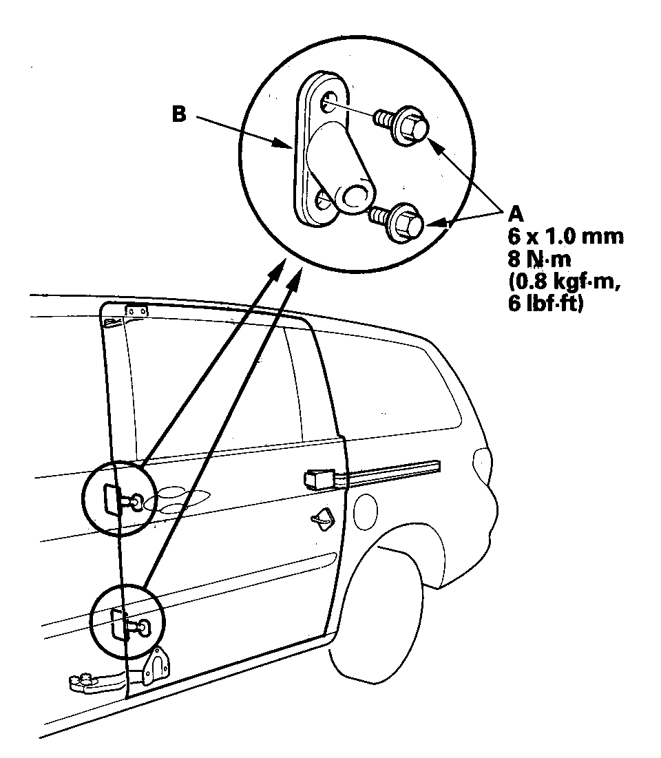
1. Remove the bolts (A), and remove both female guides (B) from the body.
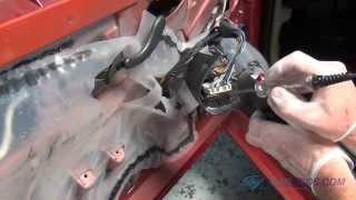
Pic 1
Vertical adjustment at the front
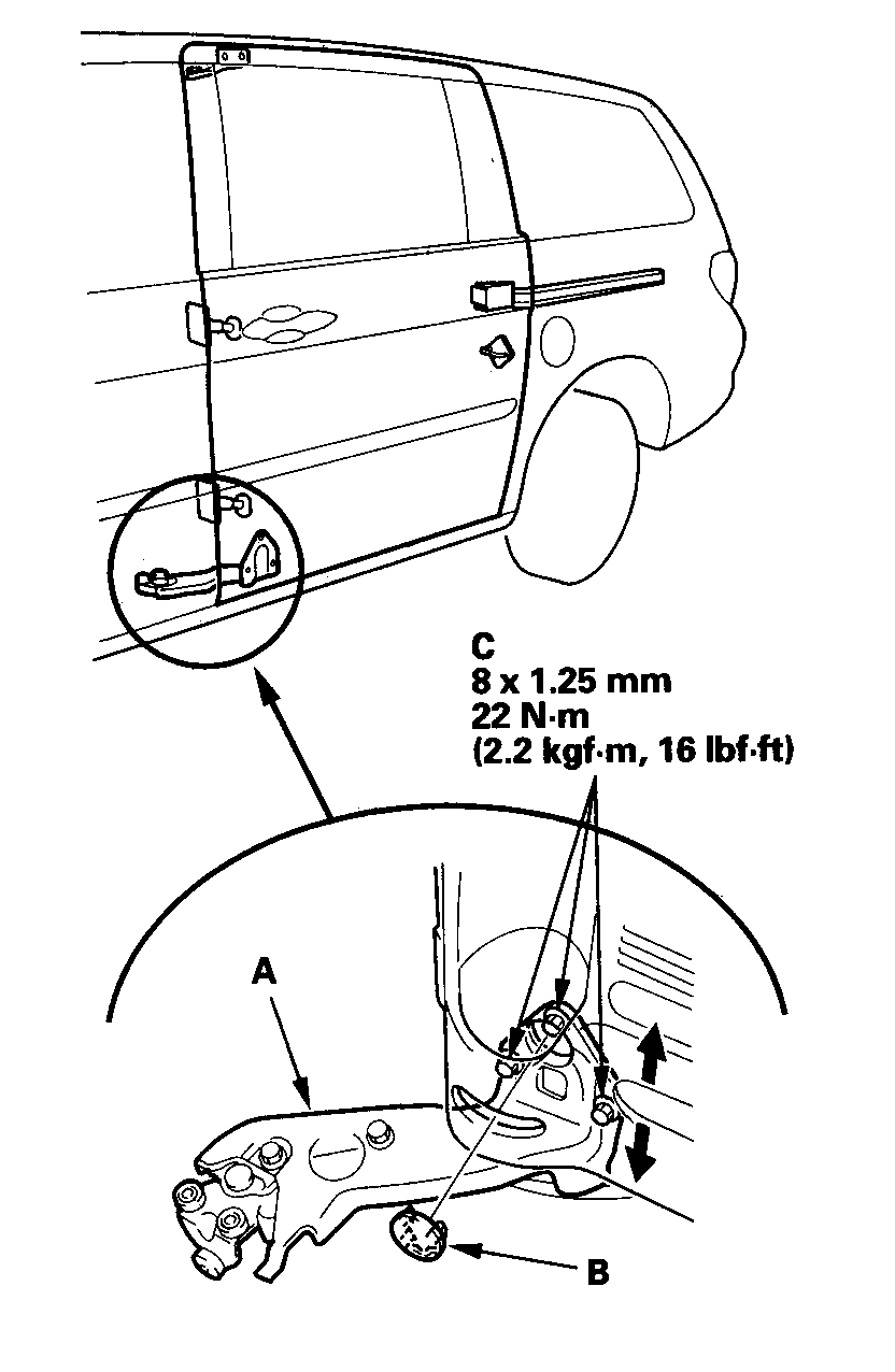
2. Adjust the lower roller (A).
1. Remove the plug (B).
2. Slightly loosen the lower roller bolts (C).
3. Move the door up or down to equalize the gaps.
4. Tighten all bolts securely, and reinstall the plug.
Pic 2
Horizontal adjustment at the front
3. Adjust the upper roller (A) and the lower roller subbase (B).
1. Slightly loosen the upper roller bolts (C), and install the shim(s) (D, E) between the upper roller and the door until the door is flush with the body.
2. Slightly loosen the lower roller subbase bolts (F).
3. Move the door in or out until it's flush with the body.
4. Tighten all bolts securely.
Pic 3
Vertical and horizontal adjustment at the rear
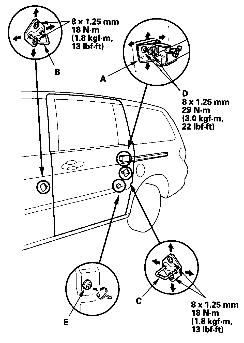
4. Adjust the center roller (A), the front striker (B) and rear striker (C).
1. Loosen the center roller bolts (D).
2. Move the door in or out until it's flush with the body, and up or down to equalize the gaps.
3. If necessary, adjust the door cushion (E) to make the door fit flush with the body.
4. Tighten all bolts and nuts securely.
Pic 4
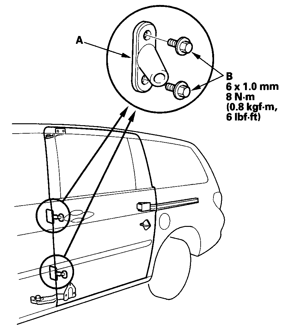
5. Set the female guides (A), and lightly tighten the bolts (B). Adjust the alignment of the guides by closing the door, then open the door and tighten the bolts.
Pic 5
6. Make sure the door opens and locks securely.
+++++++++++++++++++++++++++++++++++++++++++++
SLIDING DOOR CABLE ADJUSTMENT
Sliding Door Cable Adjustment
Outer Handle Gable A
NOTE:
- This cable is routed between the outer slide door handle and the outer handle crank assembly. It is pulled by the outside handle and rotates the linkage of the outer handle crank assembly.
- The remote control assembly needs to be off the door in order to adjust the outer handle cable A.
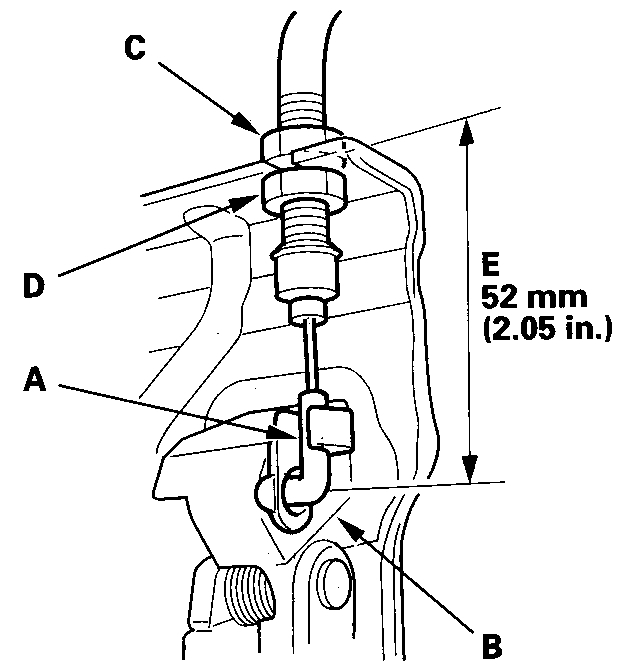
1. Connect the outer handle cable A to the outer slide door handle assembly (B), while keeping the locknut (C) and the adjusting nut (D) loose.
Pic 6
2. Set the adjusting nut so the measurement (E) is 52 mm (2.05 in.), And then tighten the locknut.
3. Route the outer handle cable A inside of the sliding door and connect it to the outer handle crank.
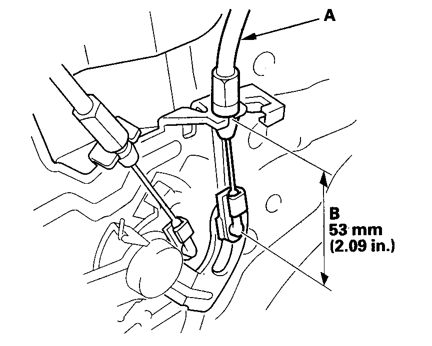
Pic 7
4. Confirm that the measurement (B) is 53 mm (2.09 in.) At the outer handle crank assembly.
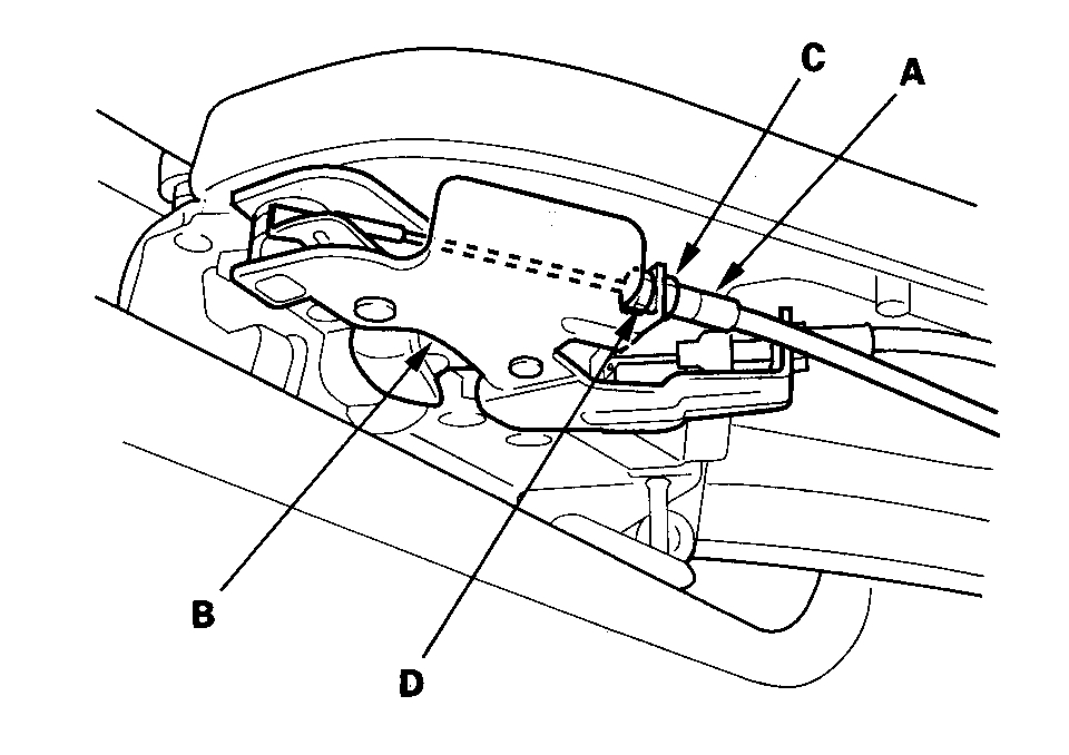
Outer Handle Cable B
NOTE:
- This cable is routed between the outer handle crank assembly and the remote control assembly. It is pulled by the outer handle crank assembly and rotates the linkage on the remote control assembly.
- Both the outer handle crank assembly and the remote control assembly need to be off the door in order to adjust the outer handle cable B.
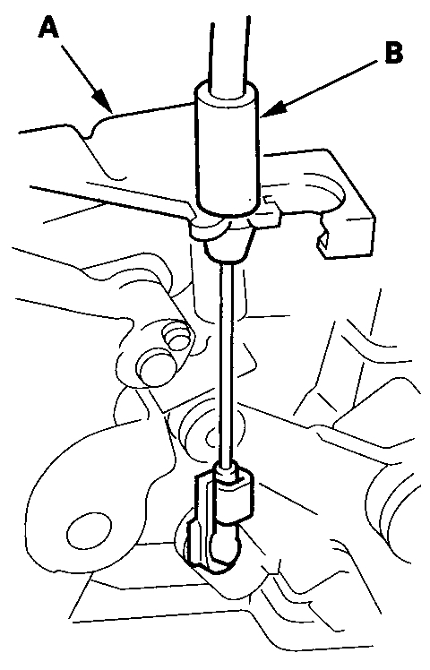
1. Connect the outer handle cable B to the outer handle crank assembly (A).
Pic 8
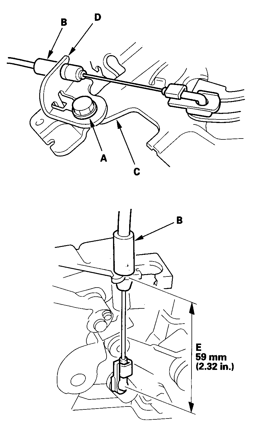
2. Loosen the mounting bolt (A), and position the other end of the outer handle cable B in the remote control assembly (C).
Pic 9
3. Adjust the cable bracket (D) so that the measurement (E) is length 59 mm (2.32 in.) At the other end of the cable, then tighten the bolt.
4. After the outer handle crank assembly and the remote control assembly are installed in the door, check the measurement again, and confirm it is still 59 mm.
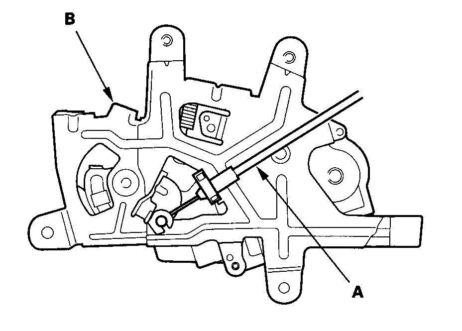
Front Latch Cable
NOTE:
- This cable is routed between the remote control assembly and the front latch assembly. It is pulled by the remote control assembly and releases the front latch to open the door.
- The outer handle crank assembly needs to be off the door in order to reach the front latch assembly.
- The cable bracket on the front latch assembly needs to be adjusted before the front latch assembly is mounted on the door.
1. Connect the front latch cable to the front latch assembly lever and bracket.
2. Adjust the cable bracket (A) so that the measurement (B) is 34 mm (1.34 in.) At the other end of the cable including the latch free play, then tighten the bolt (C).
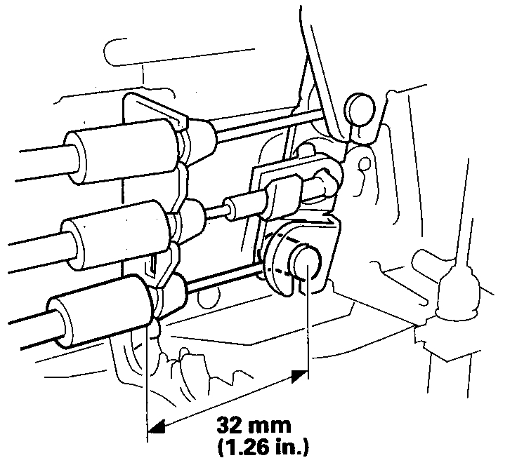
Pic 10
3. After the front latch assembly is installed on the door and the front latch cable is connected to the remote control assembly, confirm that the measurement is still 32 mm (1.26 in.).
Pic 11
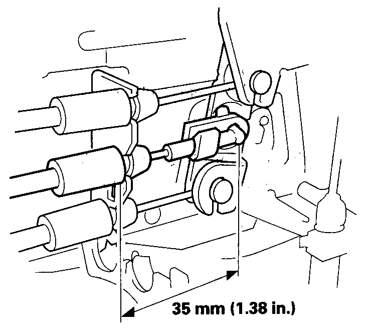
Failsafe Lever Cable
NOTE:
- This cable is routed between the remote control assembly and the rear latch assembly. It is pulled by the remote control assembly and it activates the failsafe lever.
- The rear latch assembly needs to be removed from the door in order to be able to adjust the failsafe lever cable.
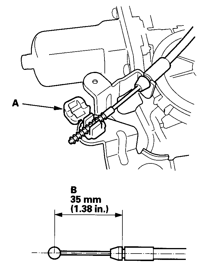
1. Connect the failsafe lever cable to the rear latch assembly lever, but keep the clip.(A) open.
Pic 12
2. Adjust the length of the cable at the clip so that the measurement (B) is 35 mm (1.38 in.) At the other end of the cable including the latch free play, and then lock the clip.
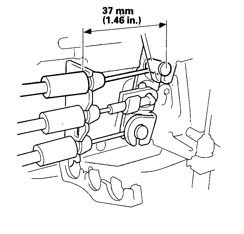
3. After the rear latch assembly is installed on the door and the failsafe lever cable is connected to the remote control assembly, check the measurement again; it should be 37 mm (1.46 in.).
Pic 13
Rear Latch Cable
NOTE:
- This cable is routed between the remote control assembly and the rear latch assembly. It is pulled by the remote control assembly and it releases the rear latch to open the door.
- The rear latch assembly needs to be, off the door in order to adjust the failsafe lever cable.
1. Connect the rear latch cable to the rear latch assembly lever and bracket.
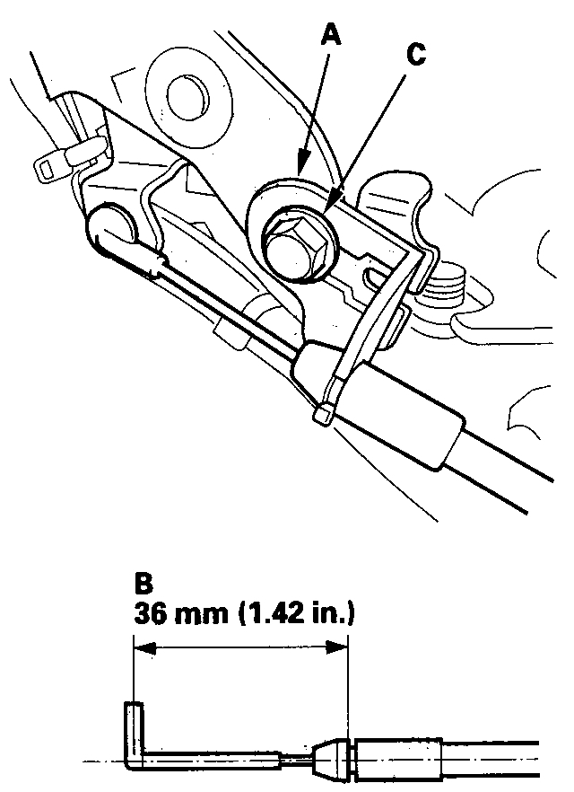
2. Adjust the cable bracket (A) so that the measurement (B) is 36 mm (1.42 in.) At the other end of the cable including the latch free play, then tighten the bolt (C). The rear latch needs to be in the fully closed position.
Pic 14
3. After the rear latch assembly is installed on the door and the rear latch cable is connected to the remote control assembly, check the measurement again; it should be 35 mm (1.38 in.).
Pic 15
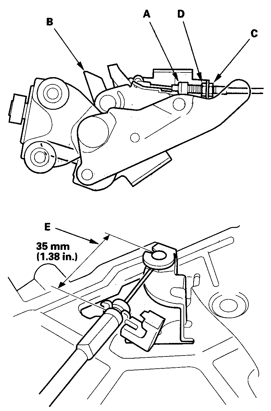
Lower Roller Latch Cable
NOTE:
- This cable is routed between the outer handle crank assembly and the lower roller latch assembly. It is pulled by the outer handle crank assembly and it releases the lower roller latch.
- Both the outer handle crank assembly and the lower roller latch assembly need to be off the door in order to adjust the lower roller latch cable.
1. Have the lower roller latch cable (A) connected to the outer handle crank assembly (B).
Pic 16
2. Set the other end of the cable (A) in the lower roller latch assembly (B) keeping the locknut (C) and the adjusting nut (D) loose.
Pic 17
3. While the lower roller latch assembly is in the closed position, set the adjusting nut so that the measurement (E) is 35 mm (1.38 in.) At the other end of the cable including the latch free play, and then tighten the locknut.
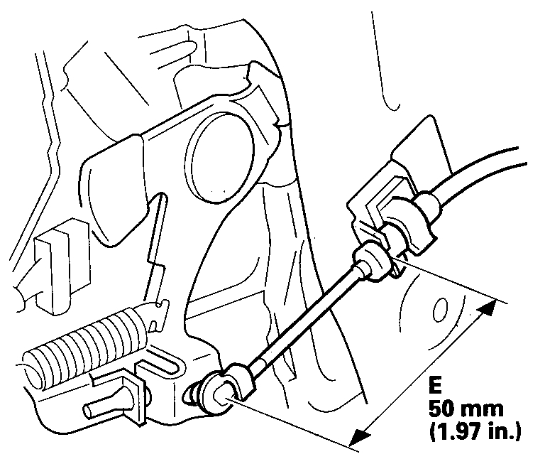
Lower Roller Stop Cable
NOTE:
- This cable is routed between the power window regulator assembly and the lower roller lever assembly. The cable is pulled by the power window regulator when the window is about 100 mm (3.94 in.) From the top; it pulls the lower roller stopper.
- The lower roller stopper cable can be easily adjusted while both, the power window regulator assembly and the lower roller lever assembly are mounted on the sliding door.
1. Position the end of the cable (A) in the lower roller latch assembly (B) keeping the locknut (C) and the adjusting nut (D) loose. Make sure the window is fully closed.
Pic 18
pic 19
2. Set the adjusting nut so that the measurement (E) is 50 mm (1.97 in.) At the other end of the cable, and then tighten the locknut.
__________________________
Let me know if this is what you needed and if it helps.
Take care,
Joe
Images (Click to make bigger)
SPONSORED LINKS
Saturday, May 11th, 2019 AT 7:57 PM