Hi,
If the crank sensor is bad, yes, you won't get spark to the plugs.
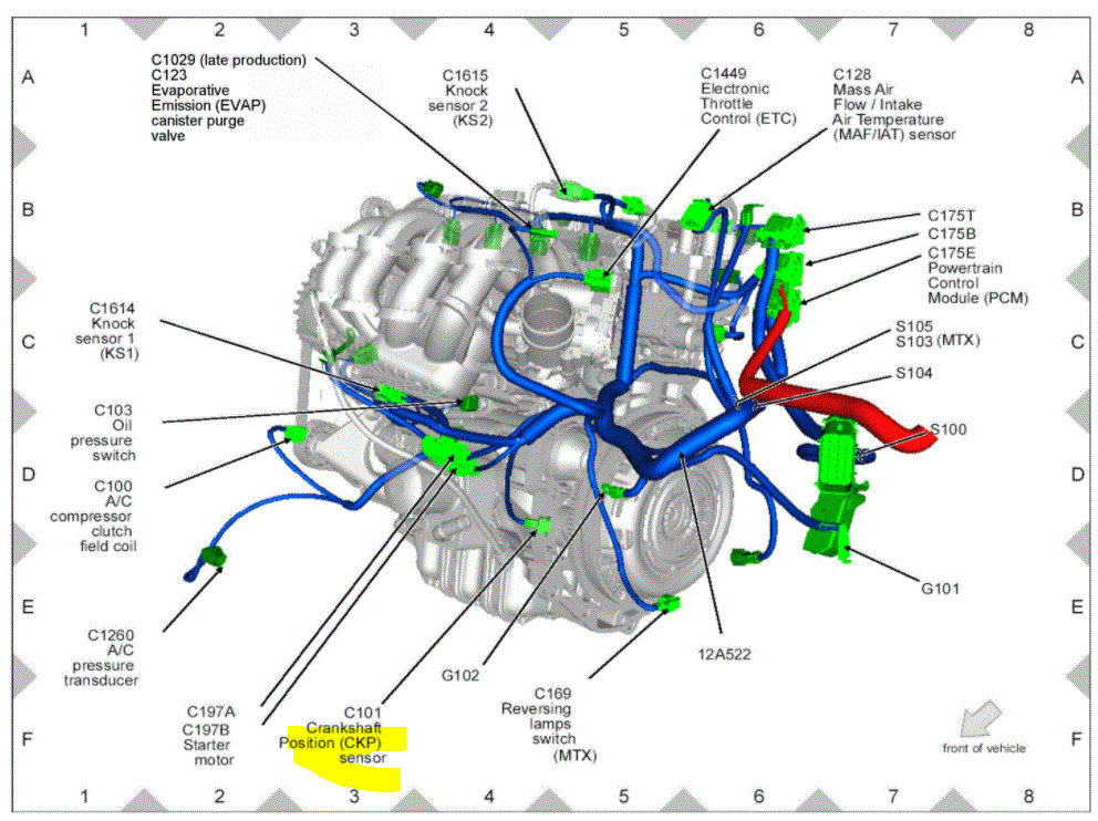
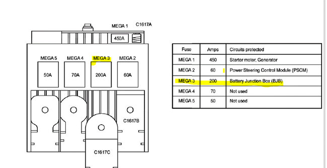
Here are directions for determining if the sensor is bad or if there is a wiring issue. This is extensive. The attached pics correlate with the directions.
___________________________________
2011 Ford Fiesta L4-1.6L
JD: Crankshaft Position (CKP) Sensor - Pinpoint Test
Vehicle Powertrain Management Computers and Control Systems Testing and Inspection Pinpoint Tests JD: Crankshaft Position (CKP) Sensor - Pinpoint Test
JD: CRANKSHAFT POSITION (CKP) SENSOR - PINPOINT TEST
JD: Crankshaft Position (CKP) Sensor
JD: Introduction See: Computers and Control Systems > Diagnostic Trouble Code Tests and Associated Procedures > JD: Crankshaft Position (CKP) Sensor - Introduction
JD1 CHECK THE CKP SENSOR SIGNAL SENT TO THE PCM
Note:The battery should be fully charged and the starting system should be functioning correctly.
- Remove the fuel pump fuse to disable the fuel pump.
- Ignition ON, engine OFF.
- Access the PCM and monitor the RPM (RPM) PID.
- Crank the engine.
Is the RPM greater than 150 RPM?
Yes
- For DTCs P0335 or P0336, GO to JD2
.
- For DTC P1336 with no start, GO to Pinpoint Test A See: Computers and Control Systems > Diagnostic Trouble Code Tests and Associated Procedures > A: No Start - Introduction
.
- For DTC P1336, GO to Pinpoint Test HD See: Computers and Control Systems > Diagnostic Trouble Code Tests and Associated Procedures > HD: Misfire Detection Monitor - Introduction
.
- For all others, the CKP, PCM, and harness are working correctly.
- RETURN to Section 3 See: Computers and Control Systems > Diagnostic Trouble Code Tests and Associated Procedures > SECTION 3: Symptom Charts
, Symptom Charts for further direction.
No
- GO to JD2
.
JD2 CHECK THE CKP SENSOR AND TRIGGER WHEEL FOR OBVIOUS PHYSICAL DAMAGE
- Ignition OFF.
- Visually check the CKP sensor and trigger wheel for physical damage.
Are any trigger wheel teeth bent more than 1.0 mm or are any parts physically damaged?
Yes
- REPAIR as necessary. RESET the keep alive memory (KAM). REFER to Section 2, Resetting The Keep Alive Memory (KAM) See: Computers and Control Systems > Diagnostic Trouble Code Tests and Associated Procedures > Resetting The Keep Alive Memory (KAM).
- For F-150 5.0L, and
- Mustang, COMPLETE the Misfire Monitor Neutral Profile Correction procedure using the scan tool.
- For all others, COMPLETE the Misfire and Fuel Monitors drive cycle procedure to learn the profile. REFER to Section 2, On Board Diagnostic (OBD) Drive Cycle See: Computers and Control Systems > Diagnostic Trouble Code Tests and Associated Procedures > On Board Diagnostic (OBD) Drive Cycle, Misfire, Fuel and Deceleration Fuel Shut Off Rear, HO2S Monitors.
No
- For F-150 3.5L, GO to JD10
.
- For all others, GO to JD3
.
JD3 CHECK FOR CORRECT CKP BIAS VOLTAGES IN THE PCM
- CKP Sensor connector disconnected.
- Ignition ON, engine OFF.
- Measure the voltage between:
pic 1
Are the voltages between 1 - 3 V?
Yes
- GO to JD4
.
No
- GO to JD6
.
JD4 CHECK THE CKP SENSOR RESISTANCE
- Ignition OFF.
- Measure the resistance between:
pic 2
Is the resistance between 0.25K - 1.1K ohms?
Yes
- GO to JD5
.
No
- INSTALL a new CKP sensor. REFER to Computer and Control Systems, Electronic Engine Controls.
- RESET the keep alive memory (KAM). REFER to Section 2, Resetting The Keep Alive Memory (KAM) See: Computers and Control Systems > Diagnostic Trouble Code Tests and Associated Procedures > Resetting The Keep Alive Memory (KAM).
- Ford F-150 5.0L, and
- Mustang, COMPLETE the Misfire Monitor Neutral Profile Correction procedure using the scan tool.
- For all others, COMPLETE the Misfire and Fuel Monitors drive cycle procedure to learn the profile. REFER to Section 2, On Board Diagnostic (OBD) Drive Cycle See: Computers and Control Systems > Diagnostic Trouble Code Tests and Associated Procedures > On Board Diagnostic (OBD) Drive Cycle, Misfire, Fuel and Deceleration Fuel Shut Off Rear, HO2S Monitors.
JD5 CHECK THE CKP HARNESS SHIELD GROUND
Note:The harness shield protects the CKP signal from electrical noise and is grounded at one end, typically near the PCM.
Note:Carry out the following resistance measurement between the CKP shield and the ground.
- Measure the resistance between:
pic 3
Is the resistance less than 5 ohms?
Yes
- GO to JD6
.
No
- REPAIR the open circuit.
- CHECK for an intermittent ground connection.
- Clear the PCM DTCs. REPEAT the self-test.
JD6 CHECK FOR SHORT BETWEEN CKP(+) AND CKP(-) IN THE HARNESS
- Ignition OFF.
- PCM connector disconnected.
- Measure the resistance between:
pic 4
Is the resistance greater than 10K ohms?
Yes
- GO to JD7
.
No
- REPAIR the short circuit. Clear the PCM DTCs. REPEAT the self-test.
JD7 CHECK THE CKP CIRCUIT(S) FOR AN OPEN IN THE HARNESS
- Measure the resistance between:
pic 5
Are the resistances less than 5 ohms?
Yes
- GO to JD8
.
No
- REPAIR the open circuit. Clear the PCM DTCs. REPEAT the self-test.
JD8 CHECK THE CKP CIRCUIT(S) FOR A SHORT TO GROUND IN THE HARNESS
- Measure the resistance between:
pic 6
Are the resistances greater than 10K ohms?
Yes
- GO to JD9
.
No
- REPAIR the short circuit. Clear the PCM DTCs. REPEAT the self-test.
JD9 CHECK THE CKP CIRCUIT FOR A SHORT TO VOLTAGE IN THE HARNESS
- Ignition ON, engine OFF.
- Measure the voltage between:
pic 7
Is any voltage present?
Yes
- REPAIR the short circuit. Clear the PCM DTCs. REPEAT the self-test.
No
- GO to JD14
.
JD10 CHECK FOR VOLTAGE AT THE SENSOR
- Ignition OFF.
- CKP Sensor connector disconnected.
- Ignition ON, engine OFF.
- Measure the voltage between:
pic 8
Is the voltage between 4.5 - 5.5 V?
Yes
- GO to JD11
.
No
- GO to Pinpoint Test C See: Computers and Control Systems > Diagnostic Trouble Code Tests and Associated Procedures > C: Reference Voltage (VREF) - Introduction
.
JD11 CHECK FOR AN OPEN IN THE HARNESS
- Ignition OFF.
- PCM connector disconnected.
- Measure the resistance between:
pic 9
Is the resistance less than 5 ohms?
Yes
- GO to JD12
.
No
- REPAIR the open circuit. Clear the PCM DTCs. REPEAT the self-test.
JD12 CHECK FOR A SHORT BETWEEN CIRCUITS IN THE HARNESS
- Measure the resistance between:
pic 10
- Measure the resistance between:
pic 11
Are the resistances greater than 10K ohms?
Yes
- GO to JD13
.
No
- REPAIR the short circuit. Clear the PCM DTCs. REPEAT the self-test.
JD13 CHECK FOR A SHORT TO VOLTAGE IN THE HARNESS
- Ignition ON, engine OFF.
- Measure the voltage between:
pic 12
Is any voltage present?
Yes
- REPAIR the short circuit. Clear the PCM DTCs. REPEAT the self-test.
No
- GO to JD14
.
JD14 INTERMITTENT CHECK
Note:Chafed CKP or CMP wires or other physical damage to the harness may cause an intermittent short in the CKP or CMP circuit.
- Ignition OFF.
- PCM connector connected.
- Visually check for chafed CKP and CMP wires or other physical damage to the CKP or CMP harness.
Is a concern present?
Yes
- REPAIR as necessary.
- Clear the PCM DTCs. REPEAT the self-test.
No
- GO to JD15
.
JD15 CHECK FOR PID CHANGE
- Ignition ON, engine OFF.
- Access the PCM and monitor the FP (PER) PID.
- Record the FP PID value.
- Connect a 5 amp fused jumper wire between the following:
pic 13
- Record the FP PID value.
Does the PID value change?
Yes
- INSTALL a new CKP sensor. REFER to Computer and Control Systems, Electronic Engine Controls.
- RESET the keep alive memory (KAM), REFER to Section 2, Resetting The Keep Alive Memory (KAM) See: Computers and Control Systems > Diagnostic Trouble Code Tests and Associated Procedures > Resetting The Keep Alive Memory (KAM).
- For F-150 5.0L, and
- Mustang, COMPLETE the Misfire Monitor Neutral Profile Correction procedure using the scan tool.
- For all others, COMPLETE the Misfire and Fuel Monitors drive cycle procedure to learn the profile. REFER to Section 2, On Board Diagnostic (OBD) Drive Cycle See: Computers and Control Systems > Diagnostic Trouble Code Tests and Associated Procedures > On Board Diagnostic (OBD) Drive Cycle, Misfire, Fuel and Deceleration Fuel Shut Off Rear, HO2S Monitors.
No
- GO to JD16
.
JD16 CHECK FOR CORRECT PCM OPERATION
- Disconnect all the PCM connectors.
- Visually inspect for:
- pushed out pins
- corrosion
- Connect all the PCM connectors and make sure they seat correctly.
- Carry out the PCM self-test.
- Verify the concern is still present.
Is the concern still present?
Yes
- INSTALL a new PCM. REFER to Section 2, Flash Electrically Erasable Programmable Read Only Memory (EEPROM) See: Computers and Control Systems > Diagnostic Trouble Code Tests and Associated Procedures > Flash Electrically Erasable Programmable Read Only Memory (EEPROM), Programming the VID Block for a Replacement PCM.
No
- The system is operating correctly at this time. The concern may have been caused by a loose or corroded connector.
________________________________
If the new sensor doesn't make a difference, this is what you will need to do.
Let me know what you find
Joe
Images (Click to make bigger)
Monday, December 7th, 2020 AT 6:36 PM


