Coolant leak knock sensor bank 2 sensor 2, where?

Tiny
BLKTAC
  • MEMBER
  • 2005 CHEVROLET SILVERADO
  • 5.3L
  • V8
  • 4WD
  • AUTOMATIC
  • 260,000 MILES
I have a bunch of questions and was hoping you could answer. Please see your video for reference. https://youtu.be/NyX6FwLYDuc?t=1086

I had a coolant leak knock sensor bank 2 sensor 2 (back of the motor) that seems to be a common thing on the 5.3 going bad. Do you know where the leak is coming from? Is it a bad seal on the intake manifold? I understand there is a seal because looking at the motor in the valley channel there doesn't appear to be coolant there, especially since the cams there are exposed which I'm fine with. I understand there are seals where the knock sensor goes thank to you and another guy on You Tub pointed them out. Any help would be appreciated.
Monday, January 16th, 2023 AT 9:01 PM

9 Replies

Tiny
BORIS K
  • MECHANIC
  • 762 POSTS
Hello,

The water entry in the knock sensor is caused by water from either engine wash or possibly rainwater.

Knock sensor 2 is usually affected.

To apply RTV sealant once the inlet manifold is removed.

How to remove intake manifold and replace knock sensors:
https://youtu.be/IOKFqzRILB4

Replace the rear bank knock sensor and build a dam (wall) around the sensor using RTV to divert water away from the sensor. See image 1 below
Apply a bead of RTV silicone sealant approximately 9 mm (3/8 in) wide and 6 mm (1/4 in) high along the outside edge of the ridge on the engine block valley cover around the rear bank knock sensor. Do Not form a complete circle. Leave the rear section open as shown.
From the underside of the intake manifold, completely remove the rear intake manifold seal (foam material).
Reinstall intake manifold

There are various brands of RTV sealant available from online retailers and automotive stores. No need to use red, high temperature, RTV.

Hope this helps.

Cheers, Boris
Was this
answer
helpful?
Yes
No
+1
Tuesday, January 17th, 2023 AT 5:43 AM
Tiny
BLKTAC
  • MEMBER
  • 5 POSTS
Good news Boris, that the advice helped. The bad news is that I forgot to torque down the knock sensors (both of them). So, I have to go back there. I noticed there are new codes, and I may have bought a bad O2 sensor (heater portion doesn't work). Then the bank 1 sensor has a connectivity issue. So the cable might be bad, may have to buy a new knock cable. Besides that, probably going to just install the oil pressure sensor and cam position sensor while I'm at it. But other than that, thanks again for the help.

Warmest Regards,

Daniel
Was this
answer
helpful?
Yes
No
Friday, January 27th, 2023 AT 11:29 PM
Tiny
BORIS K
  • MECHANIC
  • 762 POSTS
Hello Daniel,

Glad to hear that you got the knock sensors sorted.

Let us know if you need any more information.

Cheers, Boris
Was this
answer
helpful?
Yes
No
+1
Monday, January 30th, 2023 AT 2:53 AM
Tiny
BLKTAC
  • MEMBER
  • 5 POSTS
Yes, so, I kind of got it all sorted. I found out there appears to be electrical issues with the O2 sensor and the 1 bank 1 sensor. The cables on the sensor side tested fine. So, I fear it is further up the wire towards the PCM. Maybe one of the pins is bad on the PCM, I honestly don't know. I think I will have to take it into the shop for that.

Cheers.
Was this
answer
helpful?
Yes
No
Sunday, February 19th, 2023 AT 8:30 PM
Tiny
JACOBANDNICKOLAS
  • MECHANIC
  • 108,269 POSTS
Hi,

Thanks for the update. If we can help further with the wiring, please let us know. Also, if you do find the issue, we would love to hear what caused the issue. We're interested in knowing.

Take care,

Joe
Was this
answer
helpful?
Yes
No
Wednesday, February 22nd, 2023 AT 6:56 PM
Tiny
BLKTAC
  • MEMBER
  • 5 POSTS
Do you have a wiring diagram for the PCM to all the sensors? That would be great.
Was this
answer
helpful?
Yes
No
Wednesday, February 22nd, 2023 AT 8:33 PM
Tiny
BORIS K
  • MECHANIC
  • 762 POSTS
Hello,

Please see below, I had to give the wiring information in sections.
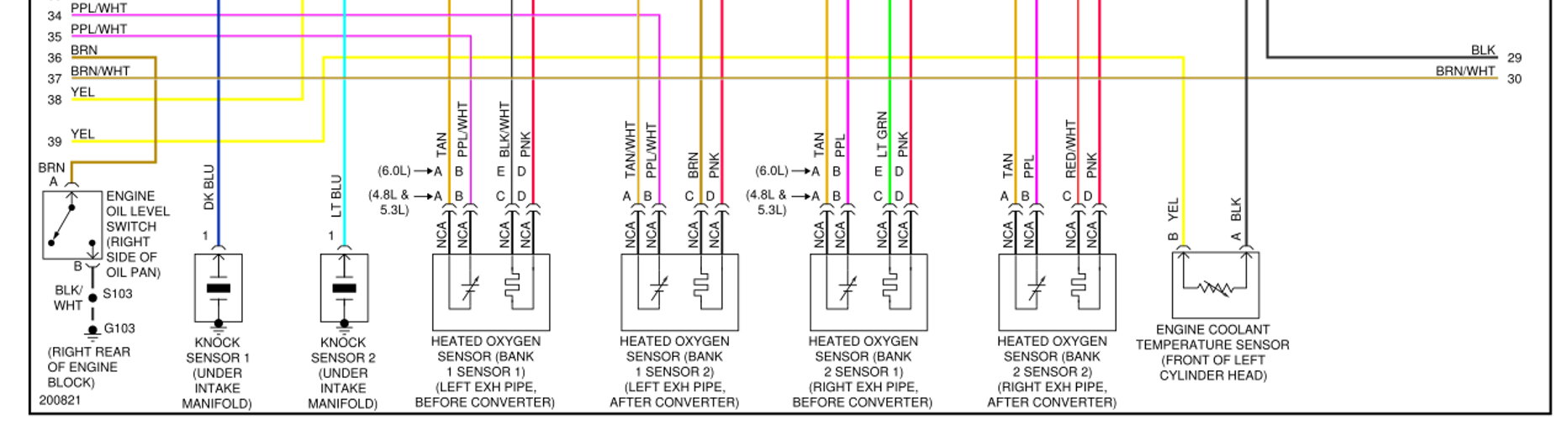
At all O2 sensors pins C+D are for the heater control, so a 12V on the pink wire (pin D) and a switched ground from the PCM at pin C.
The 12V is supplied from O2A+O2B fuses in the under-hood fuse block, see image 3.

Heater control is on pin C on each O2 sensor.
Bank 1.
Sensor 1 pin C, black/white wire to PCM pin 72 connector C2.
Sensor 2, brown wire to PCM pin 52 connector C2 .

Bank 2.
Sensor 1, light green wire to PCM pin 74 connector C2.
Sensor 2, red/white wire to PCM pin 53 connector C2.

O2 sensor signal high is from pin B at each sensor to PCM connector C1.
Bank 1 have purple/white wires and bank 2 have purple wires.
See image 4.

O2 sensor signal low is from pin A at each sensor to PCM connector C1.
Bank 1 has tan and tan/white wire, bank 2 only tan wires.
See image 5.

Suggest checking wiring from each O2 sensor connector to each pin at the PCM using a multimeter. Check the wiring for possible high resistance, short to positive or short to ground.

We should see no more than 5ohm (ideal less than 2ohm) resistance from pin to pin on each wire.

Wiring testing:
https://www.2carpros.com/articles/how-to-check-wiring

Cheers, Boris

Was this
answer
helpful?
Yes
No
+1
Thursday, February 23rd, 2023 AT 3:32 AM
Tiny
BLKTAC
  • MEMBER
  • 5 POSTS
Hey Boris,

Do you also have the diagram for the camshaft angle position sensor as well?

Warmest Regards,

Daniel
Was this
answer
helpful?
Yes
No
Thursday, March 2nd, 2023 AT 12:22 PM
Tiny
BORIS K
  • MECHANIC
  • 762 POSTS
Hello Daniel,

The CPS (Camshaft Position Sensor) has a 3-pin connector.
Pin A, brown/white wire to PCM pin 73 connector C1 Signal
Pin B, pink/black wire to PCM pin 61 connector C1 Low reference/ground
Pin C, red wire to PCM pin 39 connector C2 12V

See images 1+2 below.

The sensor is located at the back of the engine.
See image 3.

How to replace the CPS:
https://youtu.be/nUI4cDAlDJ0

Cheers, Boris
Was this
answer
helpful?
Yes
No
Sunday, March 5th, 2023 AT 1:04 AM

Please login or register to post a reply.

Sponsored links