1996 Chrysler Cirrus crank but no start

1996 CHRYSLER CIRRUS
168,912 MILES • 6 CYL • FWD • AUTOMATIC
Avatar
BOBBY LANCASTER
  • MEMBER
  • 87 POSTS
i have no spark and i have fuel pressure can here fuel pump running for 2 seconds. got about an 8 volt reading at 6 pin plug - unplugged at distributor yellow wire w/ orange tracer and both grds. were good. i was'nt getting any voltage reading from the crankshaft position sensor w/ it unplugged volt meter hooked up to the sensor and cranking engine over. also check ohm reading nothing on the old one, checked ohm reading on new one got a reading so i replaced the crank sensor thinking i had an open circut. still no spark.
Dec 26, 2009 at 3:16 PM
Advertisement
Avatar
MERLIN2021
  • CAR REPAIR CONTRIBUTOR
  • 17,250 POSTS
Unplug the cam sensor, if it starts, timing chain may need to be replaced...
Dec 27, 2009 at 6:23 AM
Avatar
BOBBY LANCASTER
  • MEMBER
  • 87 POSTS
were is cam sensor located? 1996 chrys. cirrus 2.5 eng. also i checked green w/ orange tracer to distibutor, ign. on test llight on 2 sec., crank eng. test light pulses. checked injector supply and injector pulse is good. all 6 pin conn. wires has voltage, 4.9 to 8.0 volts. checked distributor rotor rotation is good. checked grd. to ign. driver circuit get pusating voltage. is there a way to check ign. coil and ignition modual.
Dec 27, 2009 at 10:09 AM
Avatar
MERLIN2021
  • CAR REPAIR CONTRIBUTOR
  • 17,250 POSTS
Cam sensor is integral with the distributor, also I sent a tech bulliten on your distributor and engine, no ignition mod, PCM controls ignition.
Dec 27, 2009 at 12:18 PM
Avatar
BOBBY LANCASTER
  • MEMBER
  • 87 POSTS
checked btwn. ign. driver circuit and grd. w/ test light at 6 pin conn. crank eng. get pusating test light. I have good compression. timing belt ok. is there a way to check coil and and pcm. whats next step? why is it taking so long for you to answer.

Did you go on vacation?
Dec 27, 2009 at 12:39 PM
Avatar
MERLIN2021
  • CAR REPAIR CONTRIBUTOR
  • 17,250 POSTS
Did you check the info I emailed to you yet? What was the build date of your distributor? I do not do this for a living, and do have other commitments, I do not stay online all day! Sorry for the delays!
Dec 28, 2009 at 2:15 PM
Avatar
BOBBY LANCASTER
  • MEMBER
  • 87 POSTS
i do not have a hessitation on acceleration. i have a cranks no start condition. i found the imformation i needed at the auto parts, they let me look at one of there manuals. i checked resistance across 2 pin conn. at distributor got 1.1k ohms should be .6 ohms - .8 ohms. and 2 pin conn. each of the terminals at once to the coil tower and got 5k ohms. on each, should be 12k ohms - 18k ohms. checked distributor cap got 6k ohms should be 5k ohms. so im assuming coil is bad.
Dec 28, 2009 at 2:43 PM
Avatar
MERLIN2021
  • CAR REPAIR CONTRIBUTOR
  • 17,250 POSTS
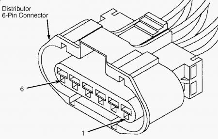
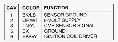
TEST NS-1A - QUALIFYING A NO START CONDITION 1. Attempt to crank engine. If engine was able to crank, go to next step. If engine was not able to crank, go to TEST NS-9A. 2. Turn ignition off, then on again. DO NOT crank engine. Using scan tool, select NO START monitor. Read current Camshaft Position (CMP) state and Crankshaft Position (CKP) state. If scan tool displays CURRENT CMP STATE PRESENT, replace CMP sensor (no signal should have been generated). Perform TEST VER-1A. If scan tool does not display CURRENT CMP STATE PRESENT, go to next step. 3. If scan tool displays CURRENT CKP STATE PRESENT, replace CKP sensor (no signal should have been generated). Perform TEST VER-1A. If scan tool does not display CURRENT CKP STATE PRESENT, go to next step. 4. While cranking engine, observe CMP and CKP state using scan tool. If scan tool shows current CKP state present, go to next step. If scan tool does not show current CKP state present, go to TEST TC-40A. 5. If scan tool shows current CMP state present, go to next step. If scan tool does not show current CMP state present, go to TEST TC-1A. 6. Go to TEST NS-1B. TEST NS-1B - QUALIFYING A NO START CONDITION 1. Disconnect cylinder No. 2 spark plug wire. Insert an insulated screwdriver in plug wire end. Hold screwdriver within 1/4" of ground. While observing for spark, crank engine for 10 seconds. Consider one or 2 sparks as a no spark condition. If good spark is present, go to TEST NS-2A. If good spark is not present, go to next step. 2. Reconnect spark plug wire. Remove distributor cap. Put one end of a spark plug wire into high tension tower of distributor. Insert an insulated screwdriver into other end of spark plug wire. Hold screwdriver within 1/4" of ground. Go to next step. 3. While observing for spark, crank engine for 10 seconds. Consider one or 2 sparks as a no spark condition. If good spark is present, replace distributor cap and rotor. Perform TEST VER-1A. If good spark is not present, go to next step. 4. Disconnect distributor 2-pin connector. Turn ignition on. Using scan tool, actuate ignition coil. Using scan tool in voltmeter mode, check voltage of ASD relay output circuit Dark NOTE: Perform all trouble code testing, that affects vehicles ability to start, before proceeding. NOTE: Steps 2) and 3) check for a stray signal. No signal should be generated. NOTE: Perform TEST NS-1A before proceeding. CAUTION: If screwdriver is more than 1/4" from ground, Powertrain Control module (PCM) damage may result. Green/Orange wire at distributor 2-pin connector. If voltage is more than 10 volts, go to next step. If voltage is 10 volts or less, repair open ASD relay output circuit. Perform TEST VER- 1A. 5. Turn ignition off. Disconnect distributor 6-pin connector. Using scan tool in ohmmeter mode, check resistance of ground circuit Black wire (not sensor ground circuit) at distributor 6-pin connector. See Fig. 50 . If resistance is less than 5 ohms, go to next step. If resistance is 5 ohms or more, repair open ground circuit. Perform TEST VER-1A. 6. Turn ignition on. Connect an analog voltmeter between ignition coil driver circuit and ground circuit at distributor 6-pin connector. See Fig. 50 . Using scan tool, actuate ignition coil. If voltmeter shows a pulsating deflection, go to next step. If voltmeter does not show a pulsating deflection, go to step 8). 7. Check engine valve timing. If engine valve timing is within specification, replace ignition coil. Perform TEST VER-1A. If engine valve timing is not within specification, repair engine valve timing as necessary. Perform TEST VER-1A. 8. Turn ignition off. Disconnect Powertrain Control Module (PCM) connector. Using scan tool in ohmmeter mode, check resistance of ignition coil driver circuit Black/Gray wire at distributor 6-pin connector. If resistance is 5 ohms or more, go to next step. If resistance is less than 5 ohms, repair short to ground on ignition coil driver circuit. Perform TEST VER-2A. 9. Using external ohmmeter, check resistance of ignition coil driver circuit Black/Gray wire between distributor 6-pin connector and PCM connector terminal No. 11. If resistance is more than 5 ohms, repair open ignition coil driver circuit. Perform TEST VER-1A. If resistance is 5 ohms or less, replace PCM. Perform TEST VER-2A. NOTE: Next step checks PCM's ability to drive ignition coil driver circuit. An analog voltmeter capable of detecting 0.1 volt is necessary to perform @test step. 12/28/2009 ...


https://images.2carpros.com/forum/automotive_pictures/62217_1_53.jpg


https://images.2carpros.com/forum/automotive_pictures/62217_3_35.jpg

Here's by the book on No Start for your car, but some steps require the chrysler DRB III tool!
Dec 28, 2009 at 2:58 PM
Avatar
MERLIN2021
  • CAR REPAIR CONTRIBUTOR
  • 17,250 POSTS
COIL TEST 1. Turn ignition off. Disconnect distributor 2-pin connector and coil wire. Using a DVOM, measure resistance of primary and secondary coil circuits. Measure primary circuit resistance between distributor 2-pin connector terminals (on distributor). 2. Measure secondary circuit resistance between each terminal of distributor 2-pin connector (on distributor) and coil tower. See IGNITION COIL RESISTANCE table. If resistance is within specification, ignition coil is okay. If resistance is not within specification, replace ignition coil.


https://images.2carpros.com/forum/automotive_pictures/62217_coilspecs_1.jpg

DISTRIBUTOR CAP A resistor is built into distributor cap. Remove distributor cap from engine. Disconnect coil wire. Using a DVOM, measure resistance between distributor cap center button and coil terminal. Resistance should be 5000 ohms. If resistance is not within specification, replace distributor cap. If resistance is within specification, distributor cap is okay.
Dec 28, 2009 at 3:03 PM
Avatar
BOBBY LANCASTER
  • MEMBER
  • 87 POSTS
thank you , yea this is what i needed. check it first thing in the morning.
Dec 28, 2009 at 5:41 PM
Avatar
BOBBY LANCASTER
  • MEMBER
  • 87 POSTS
got no spark out of high tension tower checked voltage at 2 pin conn. dark green /orange wire w/ voltmeter - pos. lead to green/ orange wire - neg. lead to eng. grd.. got less than 10 volts, 3 milli volts. next step says to repair open at ASD relay output circuit. what is that , location, schematic. Had my leads cossed, pos. lead to + pos. neg. lead to green/orange wire at 2 pin conn., got more than 10 volts. ASD relay checked good. next step.


PLEASE REPLY SOON!!!!
Dec 29, 2009 at 9:54 AM
Avatar
MERLIN2021
  • CAR REPAIR CONTRIBUTOR
  • 17,250 POSTS
ASD=Auto shutdown relay, it's in the under hood fuse block Located in position 10 Here's the diagrams and cavity #'s for testing.


https://images.2carpros.com/forum/automotive_pictures/62217_asd1_1.jpg


https://images.2carpros.com/forum/automotive_pictures/62217_asd2_1.jpg


https://images.2carpros.com/forum/automotive_pictures/62217_asd3_1.jpg


https://images.2carpros.com/forum/automotive_pictures/62217_asd4_1.jpg

Dec 29, 2009 at 1:26 PM
Avatar
BOBBY LANCASTER
  • MEMBER
  • 87 POSTS
checking coil primary, at 2 pin conn. at the distributor across the 2 terminals, on the 200 ohm scale I got 1.1 ohms, should be .06 - .08.. Checking coil secondary, on the 20k ohm scale I got 5000 ohms, should be 12,000 - 18,000 ohms. does this mean my coil is bad.


XXXXXXXXX PLEASE REPLY SOON !!!!XXXXXXXXXX
Dec 30, 2009 at 10:38 AM
Avatar
MERLIN2021
  • CAR REPAIR CONTRIBUTOR
  • 17,250 POSTS
It seems by these numbers it is, take it with you to the parts store, most can test it before you replace it. How did ASD pin 89 testing go?
Dec 30, 2009 at 1:00 PM
Avatar
BOBBY LANCASTER
  • MEMBER
  • 87 POSTS
ASD relay circuit check out good. had my leads crossed when checking 2 pin conn. green/orange wire. checking it the right way. checked out good.
Thank you so much for your help. the imformation from service manual at auto parts store was to vauge.
the imformation you gave me was systematic and tehcnical. I will see if auto parts will test the coil. you have to buy whole distributor. 250.00 bucks. Did you ever check the manufacture date on the distributor? I know your symtoms didnt match exactly, but the TSB does say other symtoms can occur, and I catagorize yours as another symtom...
Dec 30, 2009 at 1:25 PM
Avatar
MERLIN2021
  • CAR REPAIR CONTRIBUTOR
  • 17,250 POSTS
Did you ever check the manufacture date on the distributor? I know your symtoms didnt match exactly, but the TSB does say other symtoms can occur, and I catagorize yours as another symtom...
Dec 30, 2009 at 5:23 PM
Avatar
BOBBY LANCASTER
  • MEMBER
  • 87 POSTS
I dont know were to find the manufacture date for the distributor. the only numbers i found on the distributor were T5T7172 and 1917VC.
But got a distributor from junk yard for 50.00 bucks.
checked the coil seconary readings on junk yard distributor and the readings are within specs. going to install it this morning.

XXXXXXXX replacing the distributor fixed it. XXXXXX

thanks for your help. a nother satisfied customer.
HAPPY NEW YEAR !!!
Dec 31, 2009 at 7:16 AM
Avatar
MERLIN2021
  • CAR REPAIR CONTRIBUTOR
  • 17,250 POSTS
Hate to say I told you so! Happy new year!
Dec 31, 2009 at 1:20 PM
Avatar
BOBBY LANCASTER
  • MEMBER
  • 87 POSTS
where do you get your info from, chilton or haynes manual ?
Jan 2, 2010 at 12:45 PM
Avatar
MERLIN2021
  • CAR REPAIR CONTRIBUTOR
  • 17,250 POSTS
Mitchell on demand, We subscribe to a premium account that allows us to look up most cars and light trucks. Here is how you can subscribe:
https://www.2carpros.com/manuals.php
Jan 3, 2010 at 11:03 AM
Avatar
BOBBY LANCASTER
  • MEMBER
  • 87 POSTS
put distributor in started up, but got a high idle condition, idle at 2000 rpms. there was about 1/8 of movement either way of distributor could that have something to do with it.
Jan 3, 2010 at 6:10 PM
Avatar
MERLIN2021
  • CAR REPAIR CONTRIBUTOR
  • 17,250 POSTS
Might be time to check for codes. Try this and post any codes that show.
Using Malfunction Indicator Light (MIL) 1. Ensure battery is fully charged. Turn ignition on and note operation of MIL. The MIL is located on instrument panel. When ignition is first turned on, MIL should come on to verify bulb and circuit operation, and then go off. 2. Turn ignition on, off, on, off and on within 5 seconds. Record 2-digit Diagnostic Trouble Codes (DTCs) as displayed by flashing MIL. 3. For example, DTC 24 will be displayed by 2 flashes, short pause, and then 4 flashes. A short pause will exist between first and second digits on DTC. If more than one DTC is stored, after first DTC is displayed, there will be a longer pause and then another stored DTC will be displayed. 4. Once all DTCs are recorded, proceed to retrieving DTCs using scan tool to ensure all DTCs are obtained. See USING SCAN TOOL. NOTE: If MIL does not come on and then go off, bulb circuit may be defective, or problem area may exist on CCD Bus between Powertrain Control Module (PCM) and instrument cluster. If problem exists with CCD Bus, this problem may be displayed when using scan tool to retrieve DTCs.
Jan 4, 2010 at 2:37 AM
Repair Safety Notice: This information is for general instructional purposes only. Vehicle repair can be dangerous. Verify all information, follow manufacturer service procedures, use proper tools and safety equipment, and consult a qualified repair shop when needed.