Hi,
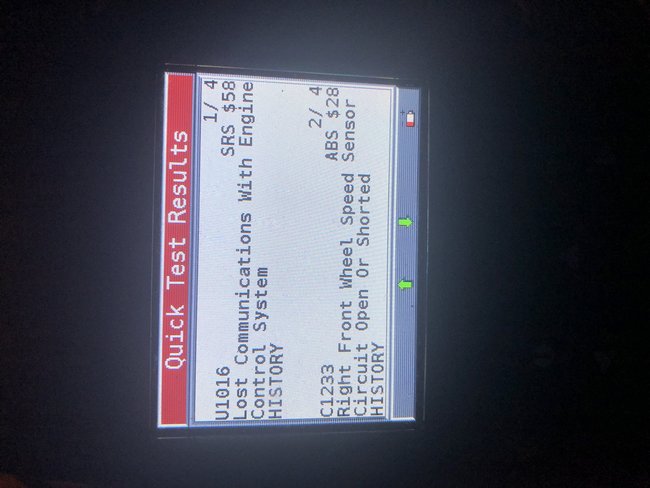
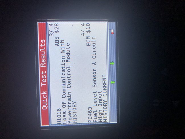
The only code relevant for it not running is the U1016. The powertrain control module is not communicating. For this code to set, it has to have power at the module, but it isn't responding to different prompts or communicating with other modules. Thus the engine won't run
__________________________________________
I am going to provide diagnostic flow charts for you. Take a look through them and see if it is something you feel comfortable doing.
__________________________________________
2001 Buick Century V6-3.1L VIN J
U1016
Vehicle ALL Diagnostic Trouble Codes ( DTC ) Testing and Inspection U Code Charts U1016
U1016
CIRCUIT DESCRIPTION
Modules connected to the class 2 serial data circuit monitor for serial data communications during normal vehicle operation. Operating information and commands are exchanged among the modules. When a module receives a message for a critical operating parameter, the module records the identification number of the module which sent the message for State of Health monitoring (Node Alive messages). A critical operating parameter is one which, when not received, requires that the module use a default value for that parameter.
Once an identification number is learned by a module, the module will monitor for the sending module's Node Alive message. Each module on the class 2 serial data circuit which is performing functions that require detection of a communication malfunction is required to send a Node Alive message every 2 seconds. When no message is detected from a learned identification number for 5 seconds, a DTC U1xxx (where xxx is equal to the 3 digit identification number) is set.
Diagnostic Chart
pic 1
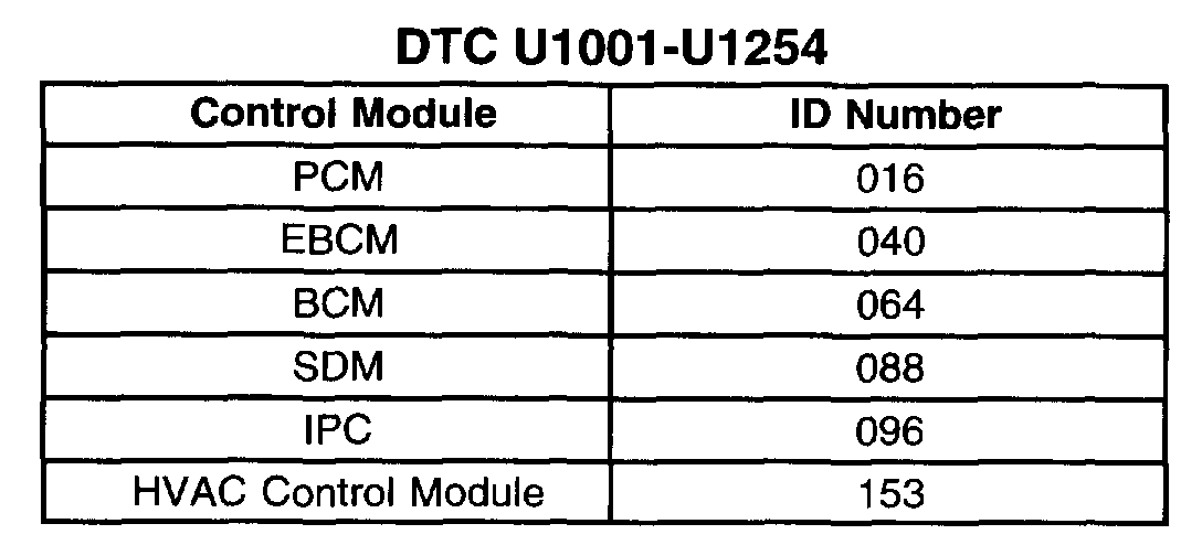
The Control Module ID Number list provides a method for determining which module is not communicating. A module with an internal class 2 serial data circuit malfunction or which loses power during the current ignition cycle would have a Lost Communication DTC set by other modules. The modules that can communicate will set a DTC indicating the module that cannot communicate. When no message is detected from a learned identification number for 5 seconds, a DTC U1xxx (where xxx is equal to the 3 digit identification number) is set.
When more than 1 Loss of Communication DTC is set in either one module or several modules, diagnose the DTCs in the following order:
1. Current DTCs before history DTCs, unless told otherwise in the diagnostic tables
2. The DTC which is reported the most times
3. From the lowest number DTC to the highest number DTC.
CONDITIONS FOR RUNNING THE DTC
Voltage supplied to the module is in the normal operating voltage range (approximately 9 to 16 volts)
Diagnostic trouble codes U1300 and U1301 do not have a current status
The module operation or vehicle power mode (ignition switch position) requires serial data communication to occur.
CONDITIONS FOR SETTING THE DTC
A message from a learned identification number has not been detected for the past 5 seconds.
CONDITIONS FOR CLEARING THE DTC
A current DTC will clear when a Node Alive message from the failed identification number is detected on the class 2 serial data circuit or at the end of the current ignition cycle
A history DTC will clear after 50 ignition switch ON/OFF cycles with no repeated failure.
TEST DESCRIPTION
Steps 1-10
pic 2
The numbers below refer to the step numbers on the diagnostic table.
1. A module which loses power supply during an ignition cycle will cause other module(s) to set Lost Communication DTCs.
2. A module which loses ground during an ignition cycle will cause other module(s) to set Lost Communication DTCs.
3. The malfunction is due to an open in the class 2 serial data circuit or an open in the module.
7. The module which was not communicating may have set Lost Communication DTCs for those modules that it was monitoring.
9. The modules which can communicate indicate the module which cannot communicate. You must clear the DTC from these modules in order to avoid future misdiagnosis.
_______________________
Here are a few links you may find helpful:
https://www.2carpros.com/articles/how-to-use-a-test-light-circuit-tester
https://www.2carpros.com/articles/how-to-use-a-voltmeter
https://www.2carpros.com/articles/how-to-check-wiring
______________________
Let me know if you need wiring diagrams or help.
Take care,
Joe
Images (Click to make bigger)
Monday, April 6th, 2020 AT 10:07 AM