ABS fault code C1155

Tiny
LT24
  • MEMBER
  • 1999 JAGUAR XJ8
  • 4.0L
  • V8
  • 2WD
  • AUTOMATIC
  • 125,000 MILES
Wheel speed front left input - circuit failure (C1155)

I need help identifying what to fix in order to clear code.

Here's what I've done so far:
- Changed the front discs and pads

- Bleed the brakes

- Cleaned the wheel speed sensors

- Cleaned the front tone rings w/wire brush

- Charged the battery

- Resoldered the 2 "cold" power joints on the ABS module

- Changed the used/tested ABS sensor cable

- Swapped out all the sensors with another used set

- Swapped out all the of the other car's wheel speed sensors with the front left (This test shows it is not a wheel speed sensor problem)

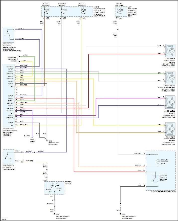
ABS light illuminates with "stability control message" on my car. I have an Autel MX808 scanner I've tried to clear code several times. It eventually always comes back up. During live data, left wheel speed sensor reads as 0 km/h but when driven up to 60 km/h, it is then consistent with other sensors. After, it continues to remain consistent from stop to go during the driving cycle.
Sunday, February 14th, 2021 AT 6:13 AM

1 Reply

Tiny
STEVE W.
  • MECHANIC
  • 13,018 POSTS
Your description and testing indicate there is a high resistance in the system between the sensor and the module. The sensors work by generating an AC voltage from the reluctor wheel passing the coil in the sensor. In this case the voltage needs to get high enough so it passes the resistance. The issue could be in the wiring or in the sensors distance from the tone ring or internal to the ABS module. A way to test it without costing money would be to swap the wires from the front sensors, right to left at the ABS module. Now drive it. If now the left (right sensor) is working properly you know the module is okay. And if the right (left sensor) is still showing faulty you know the issue is in the rest of the system. If you have access to an oscilloscope you could test the actual signal without doing any swaps, but most people don't and using a voltmeter won't really tell you anything as they are not high enough resolution to show the signal amplitude.
To swap the wiring you can either depin the connections and swap them at the connector, which is the better way as it replaces all of the harness to the sensor. Or if you think it may be just in the sensor area jack the front up, then use the scan tool and watch the reported speeds when you spin the tires by hand. Now disconnect the front sensors and just run jumper wires from the right sensor to the left connector, then watch the reported speed on the scan tool while you spin the tire. If you spin it and see nothing the wiring from their to the module is suspect, if you see the same or close speed reported as you did when the right sensor was plugged into its own harness then the issue is sensor related. A common issue on them is if any rust has built up where the sensor bolts in, it will lift the sensor away from the ring and reduce the signal. Being this is a circuit code in this case doesn't really help other than the code is saying the sensor isn't connected for a set time. That is what the speed ratings show as well. I suspect the issue is at the sensor end but if you use the swap to test the wiring from the sensor up it will show you.
Was this
answer
helpful?
Yes
No
+1
Sunday, February 14th, 2021 AT 8:32 AM

Please login or register to post a reply.

Sponsored links