Installation Procedure
1. Install the timing chain oiler nozzle and the bolt, then tighten.
Tighten: Tighten the timing chain oil nozzle bolt to 10 N.M (89 lb in).
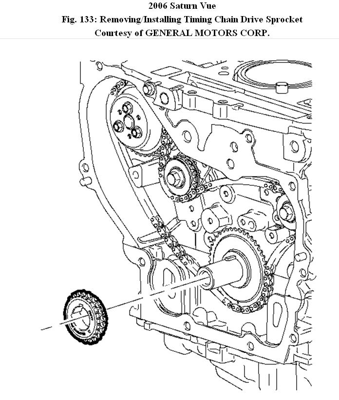
2. Install the timing chain drive sprocket to the crankshaft.
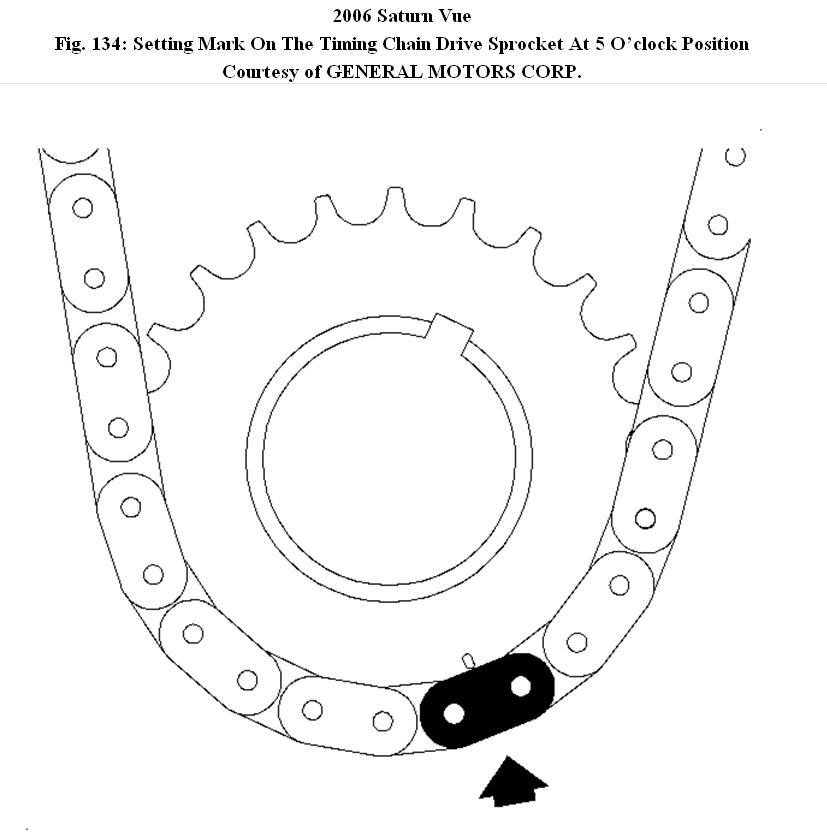
Fig. 134: Setting Mark On The Timing Chain Drive Sprocket At 5 O'clock Position
NOTE:
Set crankshaft to 60 degrees before top-dead center or after TDC to prevent valve to piston contact.
3. Using the dampener, rotate the crank so that the mark on the timing chain drive sprocket is at 5 o'clock position.
4. Set the crankshaft to 60 degrees before the top dead center.
Fig. 135: Positioning Exhaust Camshaft
5. Position the exhaust camshaft with the offset slot to 2 o'clock position.
Fig. 136: Positioning Intake Camshaft
6. Position intake camshaft with offset slot to 11 o'clock position.
7. Assemble the chain to the intake camshaft sprocket aligning the upper link to the INT diamond timing mark on the camshaft sprocket.
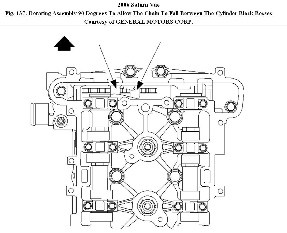
Fig. 137: Rotating Assembly 90 Degrees To Allow The Chain To Fall Between The Cylinder Block Bosses
IMPORTANT:
When lowering the timing chain into the cylinder head, rotate the assembly 90 degrees to allow the chain to fall between the cylinder block bosses, then rotate the assembly back so that the camshaft sprocket is facing forward.
8. Lower the assembly through chain housing opening on top of the cylinder head. Use care to make sure that the chain goes around both sides of the cylinder block bosses.
Fig. 138: Routing The Timing Chain Around The Crankshaft Sprocket
IMPORTANT:
The crankshaft sprocket timing mark will be at approximately
the 5 o'clock position.
9. Route the chain around the crankshaft sprocket and align the silver link to the timing mark.
NOTE:
The camshaft sprocket bolts are not reusable, it is a torque-to-yield (TTY) bolt, and must be discarded to prevent premature failure.
10. Install the intake camshaft sprocket with the chain in proper position to the camshaft. Rotate the intake camshaft using a 24 mm wrench on the flats on the camshaft until the camshaft aligns with the sprocket.
11. Install the new intake camshaft sprocket bolt and finger tighten.
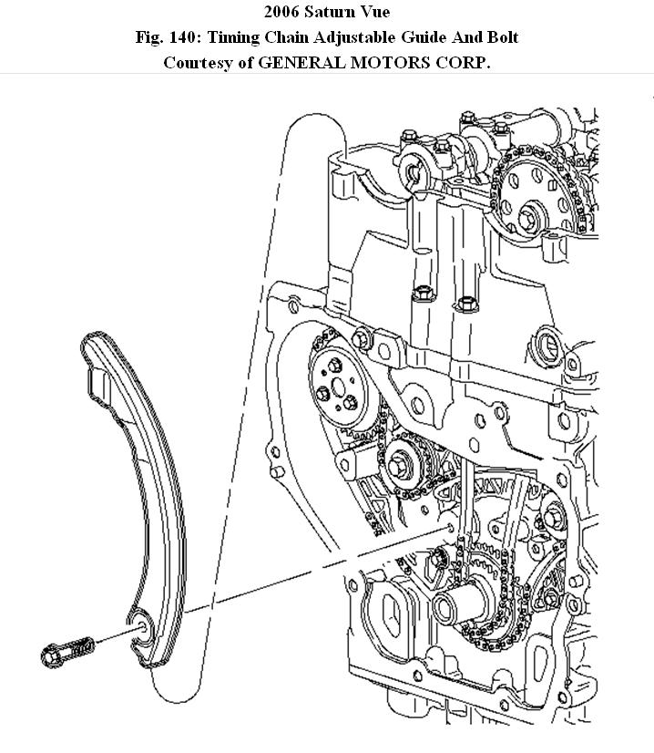
Fig. 140: Timing Chain Adjustable Guide And Bolt
NOTE:
Excess slack in the chain must be kept to the chain tensioner side (movable guide) of the cylinder block when installing the timing chain or the camshaft sprockets will not be correctly timed to the crankshaft sprocket.
IMPORTANT:
Make sure the crankshaft marks and the camshaft marks aligns with the colored links.
12. Install the adjustable timing chain guide through the opening at the top of the cylinder head and install the chain guide bolt.
Tighten: Tighten the timing chain guide (adjustable) bolt to 10 N.M (89 lb in).
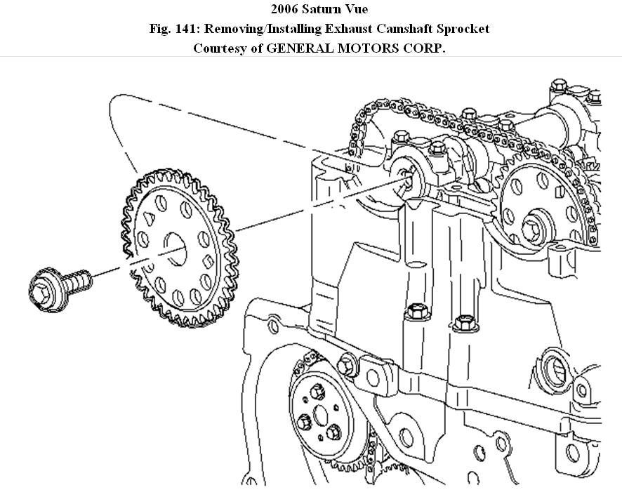
Fig. 141: Removing/Installing Exhaust Camshaft Sprocket
13. Install the exhaust camshaft sprocket loosely on the exhaust camshaft with the timing mark on the sprocket aligned with the silver link.
14. Install new camshaft sprocket bolt loosely.
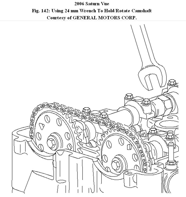
Fig. 142: Using 24 mm Wrench To Hold/Rotate Camshaft
15. Align the camshaft sprocket with the chain in proper position to the camshaft. Rotate the exhaust clockwise using a 24 mm wrench on the flats on the camshaft until the camshaft aligns with the sprocket.
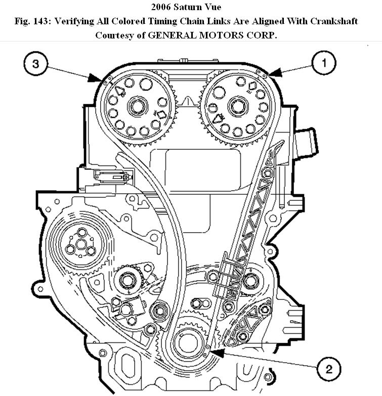
Fig. 143: Verifying All Colored Timing Chain Links Are Aligned With Crankshaft & Camshaft Marks
16. Verify that all the colored links are aligned with the appropriate intake (1), crankshaft sprocket (2), and (3) exhaust marks.
17. Verify the crankshaft sprocket timing mark is at 5 o'clock.
18. If marks are not correct, you must repeat the timing procedure.
Fig. 144: Removing/Installing Fixed Timing Chain Guide
19. Install the fixed timing chain guide and bolts.
Tighten: Tighten the timing chain fixed bolts to 15 N.M (133 lb in).
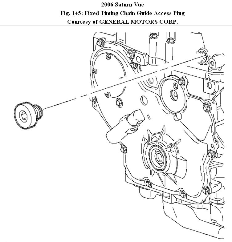
Fig. 145: Fixed Timing Chain Guide Access Plug
20. Apply the thread sealant GM P/N 12378521 (Canadian P/N 88901148) to the thread. Install fixed guide bolt access hole plug.
Tighten: Tighten the timing chain bolt access hole plug to 40 N.M (30 lb ft).
NOTE:
Use a 24 mm wrench to support the camshaft while applying torque to camshaft sprocket bolt. Do not torque camshaft bolts against timing chain, as it may damage the timing chain.
21. Tighten intake and exhaust camshaft sprocket bolts while holding camshaft with 24 mm wrench.
Tighten: Tighten the camshaft sprocket bolts to 85 N.M (63 lb ft) + 30 degrees
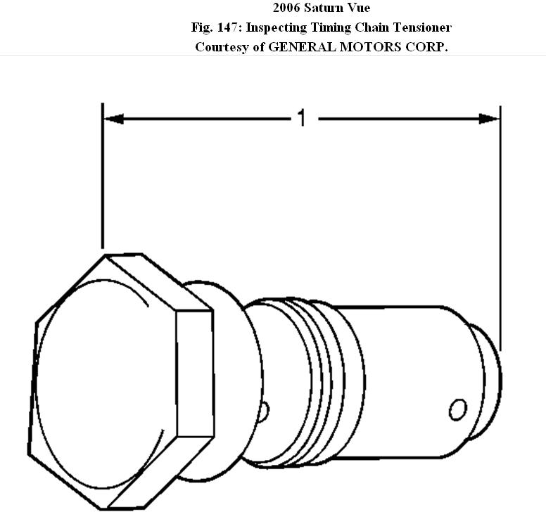
Fig. 147: Inspecting Timing Chain Tensioner
IMPORTANT:
A new tensioner should be supplied in the fully compressed non-active state. A tensioner in the compressed state will measure 72 mm (2.83 in) (1) from end to end. A tensioner in the active state will measure 85 mm (3.53 in) from end to end.
22. Inspect the timing chain tensioner. If the timing chain tensioner, O-ring seal, or washer is damaged, replace the timing chain tensioner.
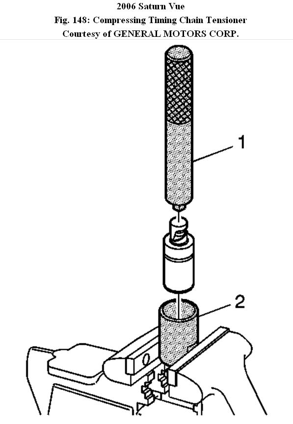
Fig. 148: Compressing Timing Chain Tensioner
23. Measure the timing chain tensioner assembly from end-to-end.
24. If the timing chain tensioner is not in the compressed state perform the following steps;
a) Remove the piston assembly from the body of the timing chain tensioner by pulling it out.
B) Install J45027-2 (2) into a vise.
C) Install the notch end of the piston assembly into the J45027-2 (2).
25. Using J45027-1 (1), turn the ratchet cylinder into the piston.
26. Inspect the bore of the tensioner body for dirt, debris and damage. If any damage appears, replace the tensioner. Clean dirt of debris out with a lint free cloth.
27. Install the compressed piston assembly back into the timing chain tensioner body until it stops at the bottom of the bore. Do not compress the piston assembly against the bottom of the bore. If the piston assembly is compressed against the bottom of the bore, it will activate the tensioner, which will then need to be reset again.
28. At this point, the tensioner should measure approximately 72 mm (2.83 in) (1) from end-to-end. If the tensioner does not read 72 mm (2.83 in) (1) from end to end repeat step 24.
29. Ensure all dirt and debris is removed from the timing chain tensioner threaded hole in the cylinder head.
30. Install the new timing chain tensioner assembly bolt and tighten.
Tighten: Tighten the timing chain tensioner assembly bolt to 75 N.M (55 lb ft).
31. The timing chain tensioner is released by compressing it 2 mm (0.079 in) which will release the locking mechanism in the ratchet. To release the timing chain tensioner, use a suitable tool with a rubber tip on the end. Feed the tool down through the cam drive chest to rest on the cam chain. Then give a sharp jolt diagonally downwards to release the tensioner.
Fig. 151: Removing/Installing Upper Timing Chain Guide
32. Install the upper timing chain guide and bolts.
Tighten: Tighten the timing chain guide (upper) bolts to 10 N.M (89 lb in).
Images (Click to make bigger)
Friday, December 31st, 2010 AT 3:34 PM