This video shows the job being done on a similar car but the process is the same.
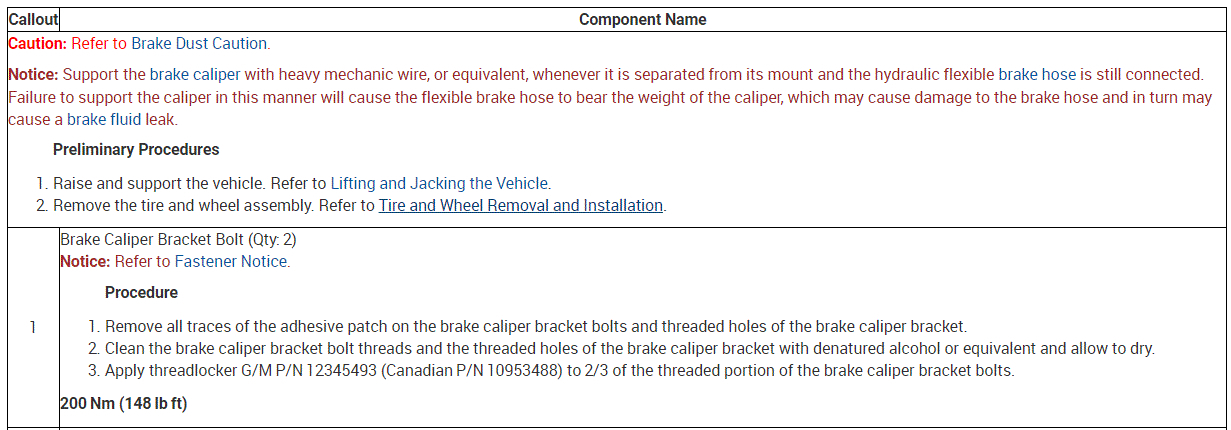
https://youtu.be/EMxfb9X3ywE
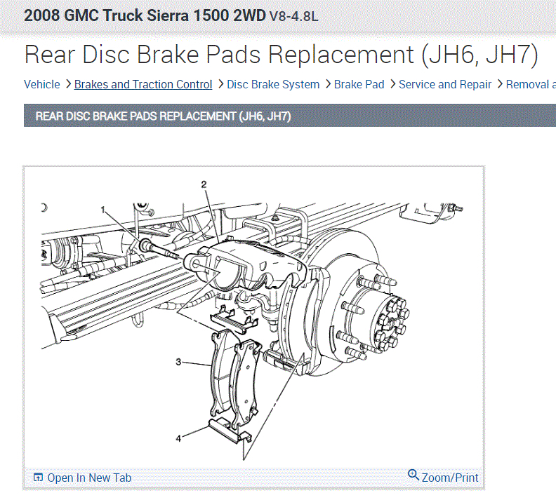
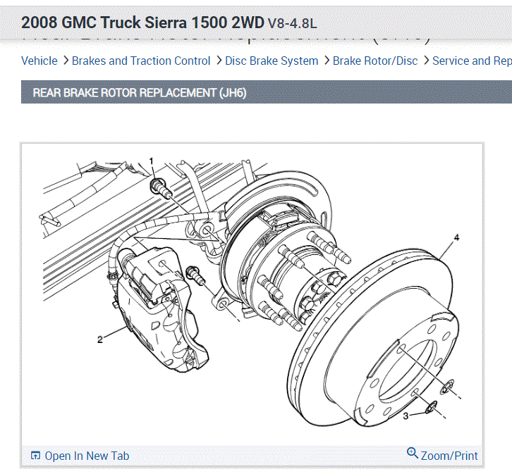
BRAKE ROTOR REPLACEMENT - REAR
Tools Required
• J 2619-01 Slide Hammer With Adapter.
• J-46277 Rotor Removal Tool.
Removal Procedure
1. Release the park brake, if necessary.
2. Inspect the fluid level in the brake master cylinder reservoir.
3. If the fluid level is midway between the maximum - full point, and the minimum allowable level, no fluid needs to be removed from the reservoir before proceeding.
4. If the fluid level is higher than midway between the maximum - full point, and the minimum allowable level, remove fluid to the midway point before proceeding.
5. Remove the tire and wheel assembly. Refer to Tire and Wheel Removal and Installation .
6. Mark the relationship of the rotor to the hub.
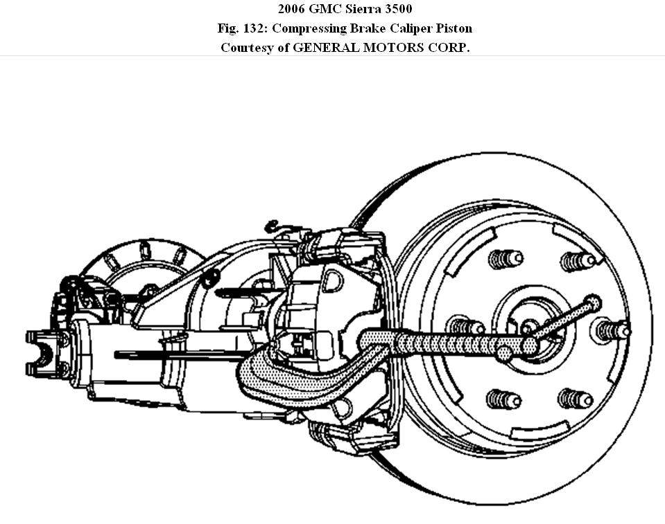
7. Compress the brake caliper pistons.
a) Install a large C-clamp over the top of the caliper housing and against the back of the outboard pad.
b. Slowly tighten the C-clamp until the pistons are pushed completely into the caliper bores.
c. Remove the C-clamp from the caliper.
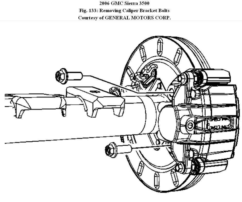
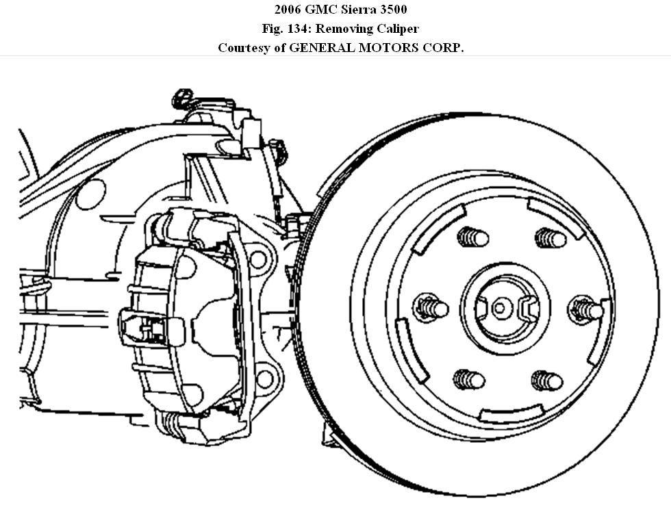
8. Remove the brake caliper bracket bolts.
9. Remove the caliper and caliper bracket as an assembly.
Support the caliper with heavy mechanic's wire or equivalent. DO NOT disconnect the hydraulic brake flexible hose from the caliper.
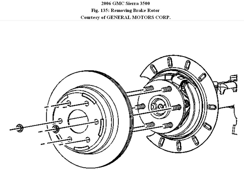
10. Remove the brake rotor retaining push nuts from the wheel studs, if applicable.
11. It may be necessary to strike the end of the hub or the rotor with a deadblow hammer to separate the rotor from the hub.
12. Remove the rotor by slowly turning the rotor while pulling the rotor away from the axle.
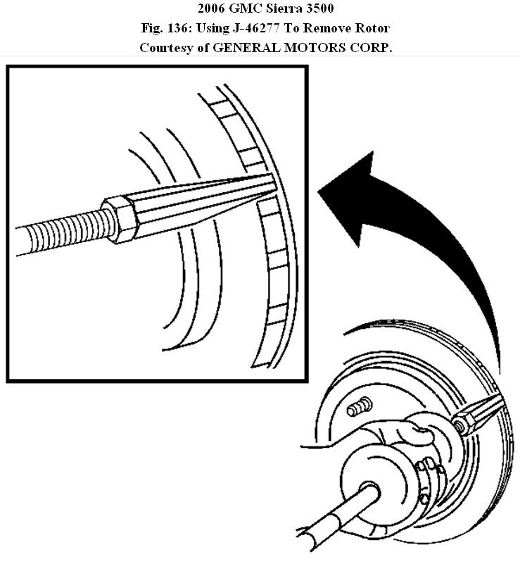
13. If the brake rotor cannot be removed, perform the following:
a) Assemble J-46277 to J 2619-01 .
b. Insert J-46277 between the rotor friction surfaces in the vent section of the rotor.
DO NOT place the J-46277 on the rotor friction surface.
c) Using J-46277 and J 2619-01 remove the rotor from the hub.
d. Inspect the park brake components for the following conditions:
• Bent or broken hold down spring
• Broken, cracked or worn brake shoe lining
• Bent or damaged brake shoe
• Worn, bent or damaged back plate
e) If any of these conditions are found replace the affected parts.
Installation Procedure
IMPORTANT:
Whenever the brake rotor has been separated from the hub/axle flange, any rust or contaminants should be cleaned from the hub/axle flange and the brake rotor mating surfaces. Failure to do this may result in excessive assembled lateral runout (LRO) of the brake rotor, which could lead to brake pulsation.
1. Use the J 42450-A to clean all rust and contaminants from the mating surface of the hub flange.
2. Use the J 41013 to clean all rust and contaminants from the inside diameter of the hat section of the brake rotor to prevent any foreign material from getting between the brake rotor and the hub flange.
3. Inspect the mating surfaces of the hub/axle flange and the rotor to ensure that there are no foreign particles or debris remaining.
4. Align the rotor to its original position on the hub, if applicable, and install the rotor.
5. If the rotor was removed and installed as part of a brake system repair, measure the assembled lateral runout (LRO) of the rotor to ensure optimum performance of the disc brakes.
6. If the rotor assembled LRO measurement exceeds the specification, bring the LRO to within specifications. Refer to Brake Rotor Assembled Lateral Runout (LRO) Correction.
7. Install the brake rotor by slowly turning the rotor while pushing the rotor towards the axle.
8. Install the caliper and caliper bracket as an assembly.
9. Perform the following procedure before installing the caliper bracket bolts.
a) Remove all traces of the original adhesive patch.
b) Clean the threads of the bolt with brake parts cleaner or the equivalent and allow to dry.
c) Apply Threadlocker GM P/N 12345493 (Canadian P/N 10953488) to the threads of the bolt.
10. Install the brake caliper bracket bolts.
Tighten:
Tighten the bolts to 200 N.m (148 lb ft).
11. Install the tire and wheel assembly. Refer to Tire and Wheel Removal and Installation .
12. With the engine OFF, gradually apply the brake pedal to approximately 2/3 of its travel distance.
13. Slowly release the brake pedal.
14. Wait 15 seconds, then repeat steps 13-14 until a firm pedal is obtained. This will properly seat the caliper pistons and pads.
15. Fill the master cylinder reservoir to the proper level with clean brake fluid, if necessary.
© 2008 Mitchell Repair Information Co., LLC.
TIRE AND WHEEL REMOVAL AND INSTALLATION
Tools Required
J 39544-KIT Complete Torque Socket Set
CAUTION:If penetrating oil gets on the vertical surfaces between the wheel and the rotor or drum it could cause the wheel to work loose as the vehicle is driven, resulting in loss of control and an injury accident.
NOTE:
Never use heat to loosen a tight wheel. It can shorten the life of the wheel, studs, or hub and bearing assemblies. Wheel nuts must be tightened in sequence and to the specified torque to avoid bending the wheel or rotor.
NOTE:
Improperly tightened wheel nuts can lead to brake pulsation and rotor damage. In order to avoid expensive brake repairs, evenly tighten the wheel nuts to the proper torque specification.
IMPORTANT:
Removing wheels can be difficult because of foreign material or a tight fit between the wheel center hole and the hub or rotor. Excessive force, such as hammering on the wheel or tire, can cause damage. Slightly tapping the tire side wall with a rubber mallet is acceptable.
1. Tighten all wheel nuts on the affected wheel.
2. Loosen each wheel nut 2 turns.
3. Rock the vehicle from side to side in order to loosen the wheel. If this does not loosen the wheel, rock the vehicle front to back applying quick hard jabs to the brake pedal to loosen the wheel.
4. Repeat this procedure if the wheel does not break free.
Removal Procedure
1. Raise the vehicle. Support the vehicle with suitable safety stands.
2. Remove the wheel center cap.
3. Remove the wheel nuts from the tire and wheel.
4. Mark the location of the tire and wheel to the hub assembly.
5. Remove the tire and wheel from the vehicle.
6. Clean the wheel nuts, studs and the wheel and rotor mounting surfaces.
Installation Procedure
CAUTION:Before installing the wheels, remove any buildup of corrosion on the wheel mounting surface and brake drum or disc mounting surface by scraping and wire brushing. Installing wheels with poor metal-to-metal contact at the mounting surfaces can cause wheel nuts to loosen. This can cause a wheel to come off when the vehicle is moving, causing loss of control and possibly personal injury.
NOTE:
A torque wrench or J 39544 must be used to ensure that wheel nuts are tightened to specification. Never use lubricants or penetrating fluids on wheel stud, nuts, or mounting surfaces, as this can raise the actual torque on the nut without a corresponding torque reading on the torque wrench. Wheel nuts, studs, and mounting surfaces must be clean and dry. Failure to follow these instructions could result in wheel, nut, and/or stud damage.
1. Install the tire and wheel. Align the locating mark of the tire and wheel to the hub.
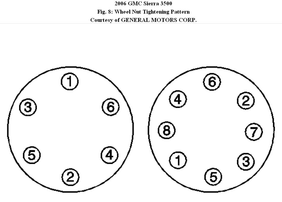
IMPORTANT:
Tighten the nuts evenly and alternately in order to avoid excessive runout.
2. Install the wheel nuts.
Tighten: Tighten the wheel nuts as shown to 190 N.m (140 lb ft).
3. Install the wheel center cap.
4. Remove the safety stands.
5. Lower the vehicle.
© 2008 Mitchell Repair Information Co., LLC.
Images (Click to enlarge)
Apr 14, 2021 at 1:37 PM
(Merged)