Hi and thanks for using 2CarPros.
Since you are able to keep it running, I suspect one of two things. An engine vacuum leak can exist when the engine is cold. However, when the engine warms up, metal expands and the leak may go away. Lets start with checking for a vacuum leak. Note, this should be done when the engine is cold and idling.
https://www.2carpros.com/articles/how-to-use-an-engine-vacuum-gauge
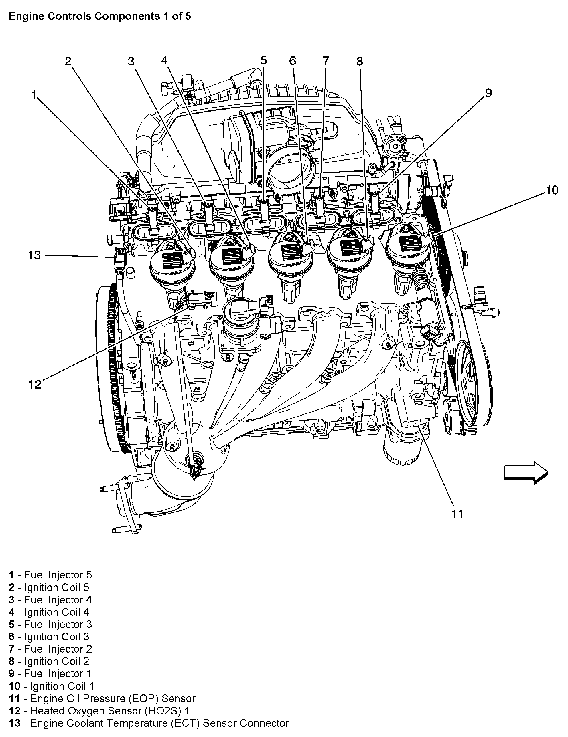
Next, the engine coolant temperature sensor sends a signal to the computer telling it the engine's temperature. Based on that information, the computer determines the air/fuel ratio needed to run the engine. If it is cold outside, the mixture is richer and opposite when warm. If the sensor is not sending the correct information, the computer will think it is warmer and lean the fuel mixture. Thus, the engine will want to stall. See picture 1 for sensor location. (number 13)
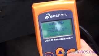
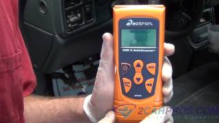
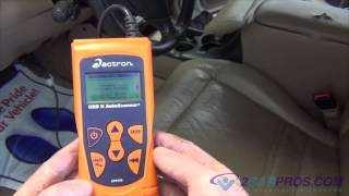
Now, the best way to check this sensor is with a live data scanner. When the engine is cold, hook up a scanner and read what temperature the sensor is telling the computer. It should be very close to the outside temperature. If it is not, the sensor is bad.
Here are general directions for coolant temp sensor replacement:
https://www.2carpros.com/articles/coolant-temperature-sensor-cts-replacement
The tough thing about these sensors is they may or may not set a trouble code if they are wrong. As long as they send a signal, the computer thinks it is working properly.
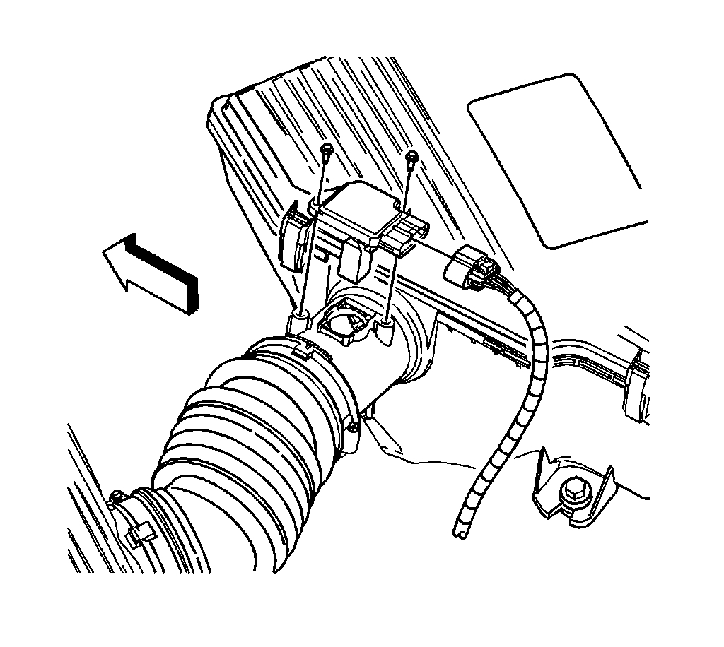
If you find the sensor is bad, here are the directions for replacing it. Picture 2 correlates with these directions.
ENGINE COOLANT TEMPERATURE (ECT) SENSOR REPLACEMENT
TOOLS REQUIRED
J 45861 ECT Sensor Socket
REMOVAL PROCEDURE
1. Partially drain the engine coolant below the level of the engine coolant temperature (ECT) sensor. Refer to Draining and Filling Cooling System (Static Fill) Draining and Filling Cooling System (Vac N Fill) in Cooling System. See: Cooling System > Removal and Replacement
2. Disconnect the ECT sensor electrical connector (2) from the following:
- The engine wiring harness
- The camshaft cover (1)
3. Using the J 45861 (4) carefully remove the ECT sensor (3) from the cylinder head (5).
NOTE: Use care when handling the coolant sensor. Damage to the coolant sensor will affect the operation of the fuel control system.
INSTALLATION PROCEDURE
NOTE:
- Use care when handling the coolant sensor. Damage to the coolant sensor will affect the operation of the fuel control system.
- Replacement components must be the correct part number for the application. Components requiring the use of the thread locking compound, lubricants, corrosion inhibitors, or sealants are identified in the service procedure. Some replacement components may come with these coatings already applied. Do not use these coatings on components unless specified. These coatings can affect the final torque, which may affect the operation of the component. Use the correct torque specification when installing components in order to avoid damage.
1. If installing the original sensor or a new sensor without sealant, apply thread sealer GM P/N 12346004 (Canadian P/N 10953480) or equivalent.
2. Using the J 45861 (4) carefully install the ECT sensor (3) into the cylinder head (5).
NOTE: Refer to Component Fastener Tightening Notice in Service Precautions.
Tighten the ECT sensor to 14 N.m (124 lb in).
3. Connect the ECT sensor electrical connector (2) to the following:
- The engine wiring harness
- The camshaft cover (1)
4. Fill the engine coolant. Refer to Draining and Filling Cooling System (Static Fill) Draining and Filling Cooling System (Vac N Fill) in Cooling System. See: Cooling System > Removal and Replacement
________________________________-
If the engine would always stall even after warm up, I would suspect a different component. Check these things first and let me know what you find or if you have other questions.
Joe
Image (Click to make bigger)
SPONSORED LINKS
Sunday, November 25th, 2018 AT 9:28 PM