You have a head light switch, a dimmer switch, and an ignition switch, and none of them are in the picture at this point, but I'm trying to understand this:
"Ok so I get power in both relays. Relay 1 treminal 1 has 13v and with the switch on terminal 3 has 12v. Relay 2 terminal 1 has 13v, switch on terminal 4 has 12v."
There are a lot of cars on which the head lights will not turn on unless the ignition switch is on. In your last reply you made mention of a switch being on, and I don't know if you're finding a different voltage at some point based on whether that switch is on of off, or whether you just happened to have the switch on and wanted include as much detail as possible.
Regardless, as I suspected a while ago, we are not working on the same things. As a former teacher, I learned, as all others do, that if you have 18 kids in class, the best-worded test questions can still get misinterpreted 18 different ways, and that's what's happening here. You can see in most of my replies that they become cumbersome with too many words, but that is necessary to make sure you're understanding what I am typing. I just finished up with a fellow with a brake problem, and in my entire reply I never referred to "the pedal". It was always, "the brake pedal". Another one I just started tonight was about "the fuel pump". I typed that about ten times. Never "the pump".
When you don't include those details, you know exactly what you're talking about, but I don't. We should have had this problem solved a week ago. This circuit is actually very basic and straight-forward. Now, for the specifics, every relay has to have four terminals. Two are for the contacts and two are for the electromagnetic coil that operates those contacts. There is an exception where horn relays often have only three terminals because one for the coil and one for the contact both have 12 volts applied all the time, so they just tie them together to simplify the socket wiring. Yours could be the same way because yours also show two terminals tied to 12 volts all the time. I was assuming, possibly incorrectly that you have the normal four terminals because the wiring diagram shows four individual terminals.
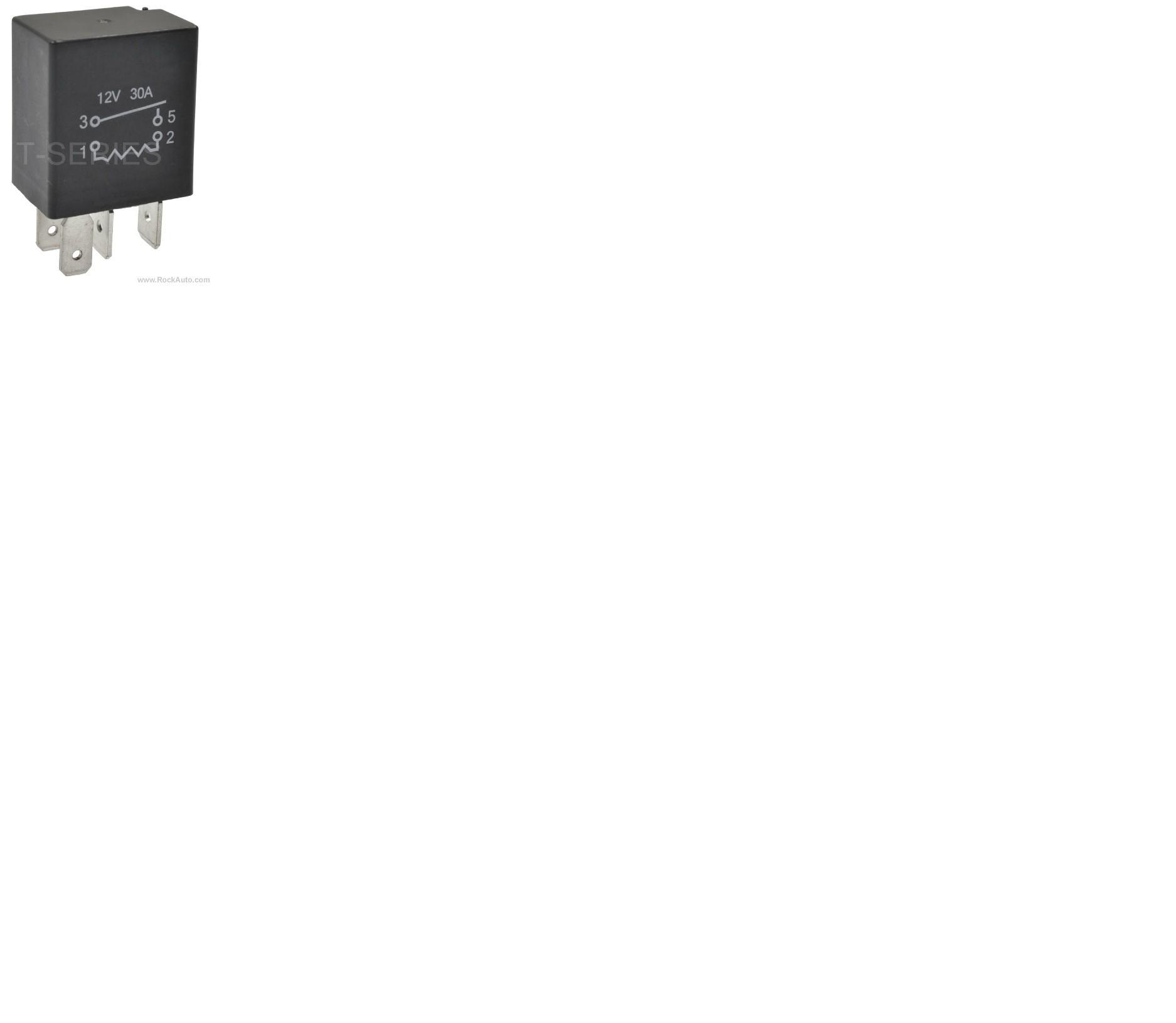
In fact, I just looked it up on the Rock Auto web site and here's a photo of what you should be seeing. Don't be confused by the "1, 2, 3, 5". Most relays of this style have five terminals with one rarely being used except for special applications.
The next problem has to do with all four of the voltage / resistance readings. There were times when my cousin and I had to work together on a tv he couldn't diagnose quickly by himself. This usually involved a 60-pin integrated circuit that we called "the bucket brigade" because it did everything. It would include a dozen different circuits that were working properly, and one that wasn't. Our procedure was for him to sit back and read the schematic diagram and tell me where to measure, then I'd tell him what I found. One of the most important details was when I found a terminal with something significantly different than what was listed, we never dropped everything else to concentrate on that one pin. We took all 60 measurements first, THEN looked at everything that was wrong. You're making that very difficult by refusing to look at all the terminals, or at least to list them. Instead, I did what I know I shouldn't do, and I gave you a bunch of tests to do with the paper clip. Doing that with just four terminals can instantly tell me if the 12 volt supplies are there, if the circuit to the dimmer switch is okay, and if, as I'm leaning toward, the wire to the head lamp switch is broken. The head lamp switch is a much better suspect but you said you replaced that already.
So now I'm left wondering how can you not have four terminals in the relay socket, and since two of them are tied together, how can you have 12 volts on only one of them. The tests I listed for you are exactly the same that my students would do on the cars I prepared for them to diagnose. As another point of interest, in an effort to ease their fears of diagnosing electrical problems, I pointed out and proved to them that by the time they got to the third charging system "bug" on the same car, or the third brake light problem, they didn't even need the service manual any more because they had the circuit memorized from the first two problems. That's what has happened to me now with your circuit. I only have to refer back to it to get the wire colors or terminal numbers. I enjoy working trough electrical problems this way, but I have a suspicion you want to drive the car and you just want to get this figured out. As I said, we should have had this done a long time ago.
My next concern is I can't see how you're getting these voltage readings. There were many times when a student got stuck, then I found he had the test light's ground clip on the battery's positive post instead of the negative one, and things like that. I had as much interest in learning what I said wrong in the classroom that allowed them to misunderstand what I wanted them to learn and do. That made me a more effective teacher every year.
To that end, I'm going to back up and unintentionally sound very sarcastic or condescending. Sorry for that. That's not my intention. I just want to know we're on the same page and that I'm using the right diagram. If you have a test light, use that rather than a voltmeter. In the case of a broken wire, a voltmeter can still pick up a tickle of voltage and give a false reading if there's a little carbon track in that break. A test light is more accurate and faster for this type of test. The test light's ground clip must be on the battery's negative post or on ay paint-free place on the body. Unpainted bolt heads are good too. I like to touch the probe to the battery's positive post or to a few fuses to be sure it's working. Once that bulb lights up, I know the ground clip is making a good contact.
I just went and looked at all the variations of this circuit, and I'm starting to think I'm using the wrong one. You said you don't have daytime running lamps and you don't have the auto-off feature. That is the only diagram that shows two relay terminals having 12 volts all the time. You're telling me only one terminal has 12 volts, and that is what could happen on the other two circuits. To add even more misery, they show differences for the daytime head lamps depending on whether the car is a "DX", an "EX", or an "LX", so you might have to tell me that too.
I see now there are only three variations, not four like I said earlier. The options are you can have only daytime running lamps, only auto-off feature, or neither of those options. You can't have both options. Both optional circuits have two different circuits feeding those two relay terminals. That would explain why you only are finding 12 volts on one terminal. If you do have one of these options, I'm going to have to visit my local Honda dealer to learn what all the abbreviations mean on the diagram, and how those computers are supposed to be diagnosed. It's 3:00 a.M. Where I am right now and I've been up for over 37 hours, ... Oh, wait. It's Sunday and they're closed. I should be navigating again by Monday!
One more tidbit. The diagrams don't list terminal numbers for the relays. If the relay in this picture is the same as the most common ones, the two terminals on the right are for the contacts. That's terminals 3 and 5 shown on the side of the relay. Check if you have numbers molded in the plastic next to the terminals and if those numbers agree. If they agree, verify again which one has 12 volts with all switches turned off. If a second terminal also has 12 volts, it's going to be on terminal 1 or 2. Those are the two on the left of the picture.
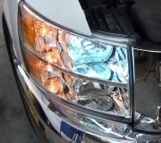
Image (Click to make bigger)
Sunday, June 7th, 2015 AT 1:29 AM