No shift into overdrive

Tiny
DRIVEAPIPER
  • MEMBER
  • 1999 LEXUS RX 300
  • 6 CYL
  • AWD
  • AUTOMATIC
  • 240 MILES
99 Lexus rx300 u140f transmission will not shift into overdrive. Code says S4 solenoid stuck or valve body plugged. Have dissected the valve body 4 times, found nothing. Replaced S4 solenoid even though it tested good, by applying power and air to verify opening and closing properly. Toyota dealer says trany is bad. Lexus dealer "we'll fix it and send you the bill!" Not to be. It refuses to shift, does not slip. In the past it has refused to shift out of second on two occasions, traced this to vvt control solenoid, cleaned them and it shifted fine. Car does not accelerate as it should and seems sluggish (mixture too rich?) I think it will not shift because the computer believes the engine is under too high a load and will not allow it to shift. Have cleaned the vvt solenoids just for grins. Any ideas from your crystal ball?
Friday, April 15th, 2011 AT 3:29 AM

7 Replies

Tiny
KHLOW2008
  • MECHANIC
  • 41,815 POSTS
What was the EXACT trouble codes that you got?
Was this
answer
helpful?
Yes
No
+2
Sunday, July 10th, 2011 AT 8:50 AM
Tiny
DRIVEAPIPER
  • MEMBER
  • 4 POSTS
For 6 months it showed PO765, hence the valve body dissection and solenoid replacement. Today it threw for the first time, PO500 vehicle speed sensor, which would fit with my feel that the computer thinks the engine is under high load and will not allow it to shift (I had the same feeling when it wouldn't shift out of 2nd due to stuck VVT solenoid). Problem now is the factory manual has no trouble shooting or test procedures for the VSS, not that I would trust a manual so full of errors as this one has proved to be (I trust nothing but the drawings for parts location). Normally, I test a part at the local parts house with a multimeter and compare it to the part in question. Only no parts house has the VSS, dealer item only. Any simple test for the VSS? Any other ideas short of rolling the dice on a dealer VSS?
Was this
answer
helpful?
Yes
No
Tuesday, July 12th, 2011 AT 3:53 AM
Tiny
KHLOW2008
  • MECHANIC
  • 41,815 POSTS
DTC P0500 : VEHICLE SPEED SENSOR (VSS) MALFUNCTION

CAUTION:
If ECM replacement is instructed in following testing, always ensure ECM harness connector and ground circuit are okay. If either are suspect, repair and repeat testing to confirm ECM malfunction. If ECM is replaced, ECM must be programmed with proper ignition key code for engine immobilizer system.

Circuit Description

Anti-Lock Brake System (ABS) Vehicle Speed Sensor (VSS) detects wheel speed and sends signals to ABS ECU. The ABS ECU converts signals into a 4-pulse signal and outputs signal to instrument cluster. Instrument cluster converts signal to a more precise waveform and outputs signal to ECM. ECM determines vehicle speed based on frequency of these pulse signals. DTC is set when ECM does not detect any VSS signal while vehicle is in motion. Possible causes are:

a) Faulty vehicle speed sensor.

B) Open or short in VSS circuit.

C) Faulty instrument cluster.

D) Faulty ECM.

Diagnostic Aids

Using scan tool, read freeze frame data. Freeze frame records engine conditions when malfunction is detected.

Diagnosis & Repair

1. Test drive vehicle and check operation of speedometer. If speedometer is not operating correctly, repair speedometer as necessary. If speedometer is operating correctly, go to next step.

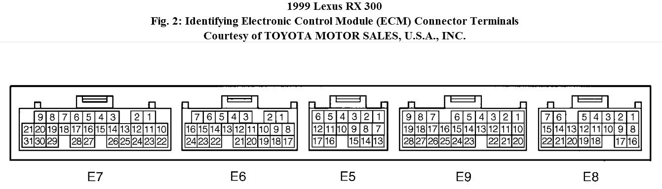
2. Access ECM behind glove box. Turn ignition off. Disconnect ECM E9
connector. See Fig. 2. Using voltmeter, check for continuity between ground and terminal No. 22 (Violet/White wire) at ECM E9 harness connector. If continuity does not exist, go to next step. If continuity exists, locate and repair short to ground in Violet/White wire between ECM E9 connector and instrument cluster.

3. Turn ignition on. Measure voltage between ground and terminal No. 22 (Violet/White wire) at ECM E9 harness connector. If voltage is 9
-14 volt, go to next step. If voltage is not 9-14 volts, locate and repair open in Violet/White wire between junction connector IJ1 and ECM. Connector IJ1 is a 16-pin connector located behind glove box.

4. Check for open in Violet/White wire between junction block IJ1 and instrument cluster. Repair wiring as necessary and retest system. If wiring is okay, replace ECM and retest system.

Is P0765 still present?
Was this
answer
helpful?
Yes
No
+3
Tuesday, July 12th, 2011 AT 11:48 AM
Tiny
DRIVEAPIPER
  • MEMBER
  • 4 POSTS
Have problem with my Lexus manual being wrong again. Mine shows the vss as a sensor mounted on the transmission. There is in fact no sensor where the manual shows it so I assume your version using the abs sensor is correct. The speedo works fine, checked against an aircraft gps for speed accuracy, it's fine. No short or open in the wire From IJ1 (J17 in my manual with no location shown). Now the mystery begins. Terminal 22 showed 4.5 volts, I unplugged IJ1 and checked the wire for continuity and short, checked fine. I plugged it back in and had 10.2 volts at terminal 22. Fine, I think so I go drive it. Same o same o no OD. I check terminal 22 again, 4.5 volts. I now unplug IJ1 and check the opposite side of the connector for power. Find 0.0 volts. Plug IJ1 back together and I have 4.5 at terminal 22. I check the front and back of IJ1 for power with the connector unplugged, 0.0 volts. My manual shows the combination meter with connector C14 v-w wire going to IJ1 and then v-w wire to the ecu terminal 22. Unplugging IJ1 should not have any effect on power on the combination meter side of IJ1, if I have 4.5 volts at terminal 22 then I should have 4.5 volts on both sides of IJ1 which I do when the connector is mated, but not when it is disconnected. Two questions. One, does your manual show anything between IJ1 and terminal 22 other than a single wire from a to b? Two, can you help me put my hands and meter on connector c-14? To further complicate the issue, the cruise control has started to work intermittently.
Was this
answer
helpful?
Yes
No
Wednesday, July 27th, 2011 AT 4:04 PM
Tiny
KHLOW2008
  • MECHANIC
  • 41,815 POSTS
The test requires 9 - 14 volts at terminal 22 an wit 4.5 volts, there should be a poor connection somewhere between the two points. When testing for voltage, the ECM has to be disconnected. 4.5 volts is wrong and you could have a faulty instrument cluster or connections from it is poor resulting in not getting the 9 - 14 volts.

No, my manual does not show anything.
Was this
answer
helpful?
Yes
No
Wednesday, July 27th, 2011 AT 5:04 PM
Tiny
DRIVEAPIPER
  • MEMBER
  • 4 POSTS
Can you help me locate connector IJ1? My manual shows it behind the glove box also, however, I have disconnected every connector behind the glove box and still have 4.5 volts on terminal 22 of connector E9 so I have not unplugged IJ1 otherwise I would have lost the 4.5 volts at E9. I would like to investigate the quality of the connection at IJ1 before removing the dash for access to the combination meter. BTW PO765 is still present. Thanks, Balding quickly.
Was this
answer
helpful?
Yes
No
Friday, July 29th, 2011 AT 9:36 PM
Tiny
KHLOW2008
  • MECHANIC
  • 41,815 POSTS
Note the wire color for the connectors and back track, that is the only way if you can't locate it.

Either you have not unplugged the connector or the wire is shorted to voltage from some source.
Was this
answer
helpful?
Yes
No
Saturday, July 30th, 2011 AT 4:04 PM

Please login or register to post a reply.

Sponsored links