1998 Toyota Tercel Fuel injectors not working.

Tiny
NUTSNBOLTS76
  • MEMBER
  • 1998 TOYOTA TERCEL
  • 1.5L
  • 4 CYL
  • FWD
  • MANUAL
  • 210,000 MILES
Hello,

This car will not start. When I first began experiencing problems, the car would just quit running occasionally and after many attempts to start, would finally start and run a few minutes to maybe twenty minutes.

Here is what I know so far.
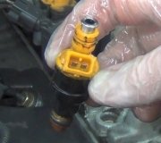
The injectors are not working. There is battery voltage at the BLK/WHT wires of each injector. Using a LED test light connected to battery positive, I'm getting no flash when touching the second wire of each injector while cranking the engine. I haven't tested continuity from the injectors to the computer yet, but that's unlikely to be the issue because each injector uses a different wire from the computer.

I disconnected each wiring harness from the computer, inspected it, and reseated it.

I cleaned and tested all grounds. Engine and multi-wire ground on back of intake.

The spark plugs are firing.

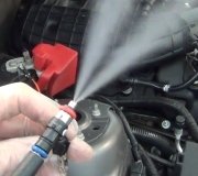
Fuel pressure is good.

I have no DTC's. The engine light is not on.

I suspect CKPS issue, MAP sensor, or ECM.

Thank you for any help. Mark H.
Monday, January 5th, 2015 AT 9:33 AM

17 Replies

Tiny
CADIEMAN
  • MECHANIC
  • 3,544 POSTS
HOOK THE TEST LIGHT TO THE NEAGITIVE BATTERY CABLE AND TEST FOR POWER TO THE INJECTORS. BECAUSE THE BLACK WIRE WITH THE WHITE STRIP IS A GROUND. FIRST CHECK THE INJECTOR FUSE IN THE FUSE PANEL TO SEE IF IT'S GOOD. TEST WITH THE KEY ON. IF GOOD THEN CK. OUTSIDE.
Was this
answer
helpful?
Yes
No
Monday, January 5th, 2015 AT 11:24 AM
Tiny
NUTSNBOLTS76
  • MEMBER
  • 8 POSTS
The fuse is good. The black/white wire is hot on this car. According to the wiring diagram I have, that wire runs to the injector fuse and ignition switch.

The other wire on each injector is a different color (1 green, 2 yellow, 3 red, 4 blue) and all run to the computer at terminals 40, 30, 20, and 10. I assume that the computer grounds these based on signals from certain sensors. I read that connecting a test light to battery positive and touching each of these wires, the test light should blink as the computer grounds each one. While cranking the engine.

I also want to add that the timing is correct on this car.
Was this
answer
helpful?
Yes
No
+1
Monday, January 5th, 2015 AT 12:29 PM
Tiny
CADIEMAN
  • MECHANIC
  • 3,544 POSTS
WILL IT RUN ON STARTING FLUID?
Was this
answer
helpful?
Yes
No
-1
Monday, January 5th, 2015 AT 1:54 PM
Tiny
NUTSNBOLTS76
  • MEMBER
  • 8 POSTS
Yes, it does run when I spray starting fluid into the intake.
Was this
answer
helpful?
Yes
No
Monday, January 5th, 2015 AT 2:22 PM
Tiny
CADIEMAN
  • MECHANIC
  • 3,544 POSTS
ONE DOES FLASH U ARE RIGHT THIS IS CONTROLLED BY THE CPU. MAKE SURE U HAVE CONTINUITY ON THOSE 4 WIRES FROM THE INJECTORS TO THE CPU. IF YES U WILL NEED TO REPLACE THE CPU.
Was this
answer
helpful?
Yes
No
Monday, January 5th, 2015 AT 3:33 PM
Tiny
NUTSNBOLTS76
  • MEMBER
  • 8 POSTS
The wires checked out good. I have ordered a computer. I'll let you know how things work out.
Was this
answer
helpful?
Yes
No
Tuesday, January 6th, 2015 AT 7:49 PM
Tiny
CADIEMAN
  • MECHANIC
  • 3,544 POSTS
Ok
Was this
answer
helpful?
Yes
No
Wednesday, January 7th, 2015 AT 12:59 AM
Tiny
NUTSNBOLTS76
  • MEMBER
  • 8 POSTS
I installed the new computer and unfortunately, the problem persists. I rechecked everything that I had previously checked and nothing had changed. What a nightmare.

When testing the two injector wires at each injector, I still have 12 volts on the black/white wires that runs to the ignition switch. I still have no pulse on my test light when testing the wires running to the computer. This time though, I checked those wires for voltage and was surprised to get a reading of 6.75 volts on each of them. If I'm correct, there shouldn't be voltage on these wires. I thought the computer grounded these wires to complete the circuit and energize the injectors.

If the crankshaft sensor were bad, what symptoms would I have? Would the injectors work? Would the spark plugs fire at the wrong time, or not at all?
Was this
answer
helpful?
Yes
No
Friday, January 9th, 2015 AT 6:29 PM
Tiny
CADIEMAN
  • MECHANIC
  • 3,544 POSTS
SORRY TO HEAR THAT. ARE U READING 6.75V AT THOSE WIRES FROM THE COMPUTER TO THE INJECTORS ALSO. DO U SEE ALL 4 WIRES COLORS FROM THE COMPUTER AT THE INJECTORS. FIND THE INJECTOR RELAY AND SWITCH WITH ANOTHER RELAY. THE CRANK SENSOR CAN TAKE THE INJECTOR SIGNAL BUT I'M NOT SURE. WHAT COLOR WIRES GO TO THE CENTER OF THE INJECTORS. BECAUSE THAT WIRE IS THE POWER WIRE. THE OTHER WIRE IS THE GROUND.
Was this
answer
helpful?
Yes
No
Friday, January 9th, 2015 AT 8:19 PM
Tiny
NUTSNBOLTS76
  • MEMBER
  • 8 POSTS
I'm sorry, maybe I'm not explaining things clearly.

Each injector has a black/white wire. According to my wiring diagram, these wires tie together at some point and run to the ignition switch. I am getting a reading of around 12 volts on these black/white wires. There is no relay between the injectors and the ignition switch.

The second wire of each injector is a solid color of green, yellow, red or blue. These wires all run directly to the computer. There is no relay between these wires and the computer. I'm getting a reading of 6.75 volts on each of these wires.

Black/White wires = 12 volts
Colored wires = 6.75 volts

Continuity is good on the colored wires running to the computer. It almost seems as though voltage is somehow feeding back from somewhere, through the computer, to the colored wires running to the injectors.

I can not find an injector relay.

Would it help you any if I emailed a copy of the wiring diagram to you?
Was this
answer
helpful?
Yes
No
Saturday, January 10th, 2015 AT 7:47 AM
Tiny
CADIEMAN
  • MECHANIC
  • 3,544 POSTS
BOTH THE WIRES CAN'T HAVE POWER ONE HAS TO BE A GROUND. MAIL ME THAT DIAGRAM TO SEE IF I CAN EVEN HELP U. THE INJECTOR HARNESS HAS TO BE SHORTED SOME WHERE IN THE ENGINE COMPARTMENT. EMAIL IS ccraigsteeves@yahoo. Com
Was this
answer
helpful?
Yes
No
Saturday, January 10th, 2015 AT 8:16 AM
Tiny
NUTSNBOLTS76
  • MEMBER
  • 8 POSTS
I emailed the diagram.

I'll unplug the harness from the computer and see if I'm still getting voltage on the colored wires.
Was this
answer
helpful?
Yes
No
Saturday, January 10th, 2015 AT 8:45 AM
Tiny
CADIEMAN
  • MECHANIC
  • 3,544 POSTS
ON THE FIRST DIAGRAM YOU SEE A 5AMP IGNITION FUSE ON THE INSIDE FUSE PANEL CK. IT.
THEN TO RIGHT OF THAT ON THE DIAGRAM U WILL SEE THE EFI RELAY AND A 15 AMP. FUSE. THIS IS IN THE ENGINE COMPARTMENT FIND IT AND CK. THE FUSE IF GOOD AND IS GETTING VOLTAGE REPLACE THE RELAY. THEN THERE SHOULD BE NO POWER TO THE BLACK AND WHITE WIRE BECAUSE IT IS A GROUND.
Was this
answer
helpful?
Yes
No
Saturday, January 10th, 2015 AT 10:44 AM
Tiny
NUTSNBOLTS76
  • MEMBER
  • 8 POSTS
I'm getting 12 volts on the black/white wire that runs to the ignition switch. Everything is good on that side. This car uses a negative trigger circuit in which the wire from the ignition switch is always hot when the ignition switch is in the on position and the computer grounds the colored wires running to it. I just need to figure out the problem on the negative side. I haven't had a chance to do more testing yet due to having to work on it out in the weather. I'm normally petty good at tracking down wiring issues, but this one has been tough.
Was this
answer
helpful?
Yes
No
Monday, January 12th, 2015 AT 7:08 AM
Tiny
CADIEMAN
  • MECHANIC
  • 3,544 POSTS
U need to go under the hood and find the efi relay (electronic fuel injection relay) their will be a 15amp. Fuse their u will need to ck. It to or u are never going to fix it. It's on one of the fender wells.
Was this
answer
helpful?
Yes
No
Monday, January 12th, 2015 AT 7:37 AM
Tiny
NUTSNBOLTS76
  • MEMBER
  • 8 POSTS
All of that was good. I finally found the problem. There was a break in one of the brown ground wires that run from the computer to a collection of ground wires on the back of the intake manifold. The break was about five inches from the connection at the manifold, just before it enters the main big wiring harness. Because there was no ground, the EVAP solenoid couldn't energize and voltage was travelling from the EFI relay, through the EVAP solenoid, to the computer. This is why I had voltage on the colored wires from the computer to the injectors. The voltage dropped from 12 volts to about 7 volts through the EVAP solenoid. I'm explaining all of this in hopes that this conversation will be available online in case others run into this issue.

I appreciate your help. I'm sure glad to finally be done with that car, although I did learn some from this adventure. Luckily, I was able to get that computer used and pretty cheap, so I wasn't out much money on it.
Was this
answer
helpful?
Yes
No
Wednesday, January 14th, 2015 AT 9:04 PM
Tiny
CADIEMAN
  • MECHANIC
  • 3,544 POSTS
BINGO I'M VERY HAPPY FOR U. I NOW CERTIFY U IN TRACING AND REPAIRING A OPEN CIRCUIT. GOOD LUCK IN THE FUTURE AND REMEMBER IF THE PROBLEM ISN'T ON THE POWER SIDE IT'S ON THE GROUND SIDE.
Was this
answer
helpful?
Yes
No
Wednesday, January 14th, 2015 AT 10:39 PM

Please login or register to post a reply.

Sponsored links