Hello,
1. Allow engine to cool, disconnect battery negative cable, disconnect positive cable, remove battery and battery tray, disconnect all electrical harness connectors and hoses to intake manifold. Remove throttle cover, remove throttle and cruise control cables, remove air cleaner assembly and intake air duct.
2. Drain coolant, to prevent cylinder head damage, do not remove cylinder head until coolant temperature is less than 100F(38c).
3. Remove intake manifold check (fig1) below.
4. Remove exhaust manifold check(fig2) below.
5. Rotate crank shaft clockwise until, # 1 piston is at TDC of compression stroke. Using a jack, support engine prior to removing center bracket. Place a cushion between oil pan and jack. Remove center bracket.
6. Loosen mounting bolts and adjusting rod, and then remove generator belt. Loosen idler pully center nut and adjusting bolt, and then remove A/C compressor belt. Loosen mounting nut/bolt and adjusting bolt. And then remove power steering pump belt.
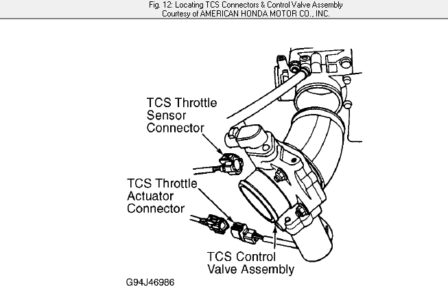
7. Remove traction control system upper and lower brackets. Disconnect TCS throttle sensor and actuator connectors. Remove TCS control valve assembly see(fig3)below. Do not remove breather pipe by pass hose. Remove engine wiring harness cover. Remove oil pressure switch connector. Remove engine ground cable.
8. Remove idler pulley, dipstick and tube. Remove crank pully, remove upper and lower timing belt covers see (fig4)below. If reusing timing belt mark direction of belt rotation for installation reference. Loosen timing belt tensioner adjusting bolt 180 degrees. Push tensioner to release belt tension. And then retighten adjusting bolt. Remove timing belt.
9. Remove upper radiator hose and water bypass hoses. Remove vacuum hoses, and then remove clamp from under hood fuse/relay box. Remove battery cables from under hood fuse/relay box. And then remove under hood fuse/relay box. Remove engine wiring harness connector.
10. Disconnect connectors, then remove control box, vacuum hose and solenoid valve. Disconnect brake booster vacuum hose. Release fuel pressure, remove fuel feed hose, fuel return hose, vacuum hose, and EVAP control canister hose. Remove water by pass hoses and heater hose.
11. Remove engine ground cable and wiring harness clamps. Remove PCV hose. Remove bolt retaining A/T dipstick bracket. Disconnect all electrical harness connectors and hoses to cylinder head. Remove inlet pipe mounting bolts from right cylinder headcover. Remove vacuum hoses and breather hose.
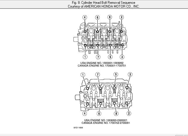
12. Remove ignition coil packs from right and left head covers. Remove left and right camshaft pulleys, then remove left and right back covers. Remove crank/cylinder sensor from left cylinder head. Remove left and right cylinder head covers. Remove generator mounting bracket bolts and power steering pump mounting bolts. Remove cylinder head bolts, in squence, 1/3 turn at a time, repeat procedure until all bolts are loose. See (fig5)below. Remove cylinder head.
Inspection:
clean gasket mating surfaces. Check camshaft to holder oil clearance. Cylinder head cannot be resurfaced if clearance is not within specification see (fig6)below.
Measure cylinder head warpage. If warpage is less than 0.002(0.05mm), resurfacing is not required. If warpage is 0.002-0.008(0.05-0.02mm), resurface cylinder head. Maximum resurface limit is 0.008(0, 2mm). Remove and clean oil control orfices see (fig7).
Installation.
1. To install, reverse removal procedure ensure cylinder heads and cylinder block surface are clean. Install left and right exhaust manifolds using new gaskets. Apply oil to threads of exhaust manifold self locking nuts. Using crisscross pattern. Tighten locking nuts to specification in 2 or3 steps, starting with inner nut, see (fig8). Install exhaust manifold covers.
2. Install oil control orifices with new O rings. Install cylinder head dowel pins with new cylinder head gaskets. Ensure oil control orifices and dowel pins are aligned.
3. Install cylinder heads on engine block. Apply clean engine oil to cylinder head bolts threads and washer contact surfaces. Tighten cylinder head bolts to specification, in sequence in 2 or 3 steps see (fig8).
4. Apply liquid gasket sealer to indicated area(head mating surface of No 1 and 7 camshaft holders USA engine No 1300001-1309262 and canada engine NO 1700001-1700751. No1 and 5 camshaft holders USA engine No 1309263-2300001 and canada engine No 1700752-2700001). See (fig9). Install cylinder head covers.
5. To install engine belt, ensure No 1 piston at TDC of compression stroke. Position crankshaft and camshaft pulleys as as shown prior to timing belt installation see (fig 10).
6. Install timing belt onto crank pulley, tension adjuster pulley, left camshaft pulley, water pump pulley, and right camshaft pulley in that order see (fig11). Loosen and retighten timing belt idler pulley adjusting bolt to tension the timing belt. Install crankshaft pulley rotate crankshaft clockwise 5-6 turns to properly position timing belt on pulleys. Adjust timing tension.(Fig11).
7. Remove crankshaft pulley. Install lower cover. Install crankshaft pulley, rotate crankshaft clockwise until No 1 piston is at TDC of compression stroke. Verify timing marks are aligned. If timing marks are not aligned repeat timing belt installation procedure. Adjust generator belt, A/C belt, and power steering pump belt tension. To complete installation, reverse removal procedure.
Hope these helps.
Thank you.
Images (Click to make bigger)
SPONSORED LINKS
Monday, January 25th, 2021 AT 12:41 PM