Hi and thanks for using 2CarPros.
First, I hope I'm answering this correctly. You mention rear and then knuckle which is on the front. So I think you are referring to the front ABS sensor on the rear of the steering knuckle. If that is wrong, please let me know. Also, the hub bearing is a pressed in bearing on this vehicle. It isn't a hub bearing assembly that bolts on.
So, there is only one type of hub assembly for this vehicle. The sensor bolts to the rear of the steering knuckle. The sensor has a non removable wire attached to it that plugs in to the vehicle's wiring harness. The sensor itself is removable from the steering knuckle.
With that in mind, here are directions for replacing the hub assembly. The attached pictures correlate with these directions.
_______________________________________________________
FRONT AXLE HUB LH REPLACEMENT
REPLACEMENT
HINT: Replace the RH side by the same procedures with LH side.
1. REMOVE FRONT WHEEL
Picture 1
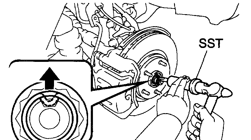
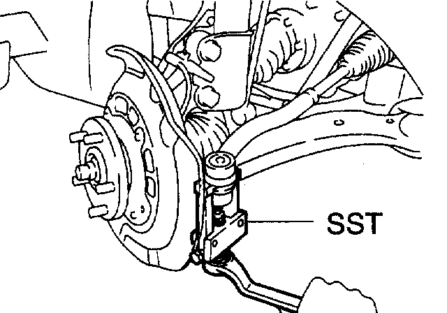
2. REMOVE FRONT AXLE HUB LH NUT
a. Using SST and a hammer, unstake the staked part of the lock nut.
SST 09930-00010
b. While applying the brakes, remove the lock nut.
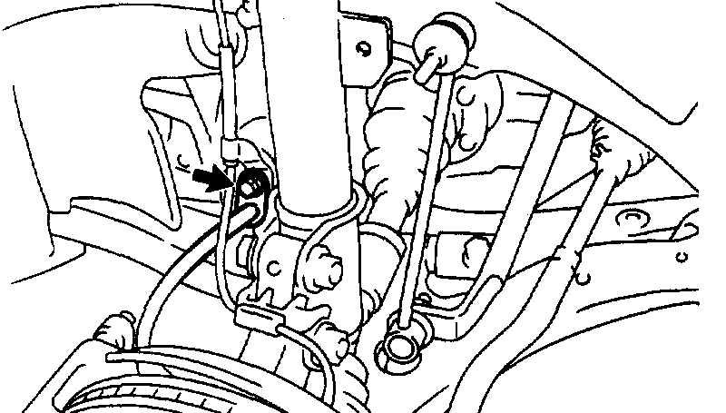
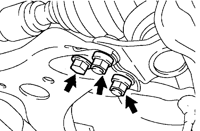
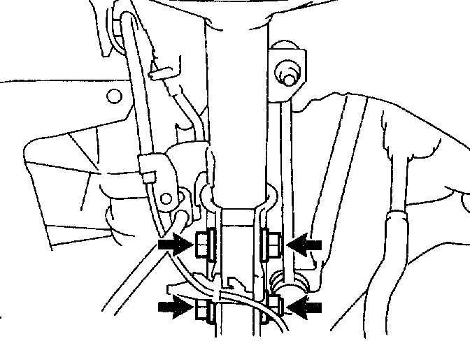
3. SEPARATE SPEED SENSOR FRONT LH
Picture 2
a. Remove the bolt, separate the sensor wire and flexible hose from the shock absorber.
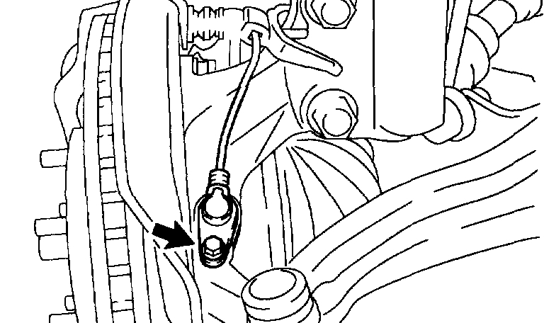
Picture 3
b. Remove the bolt and separate the speed sensor from the steering knuckle.
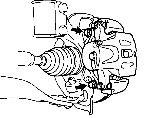
Picture 4
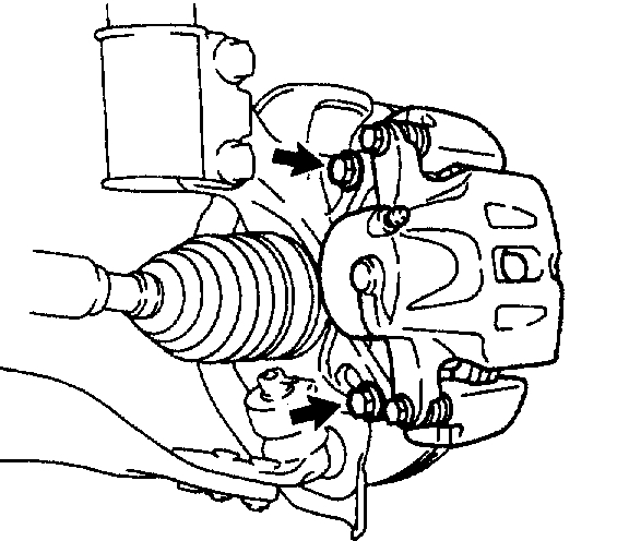
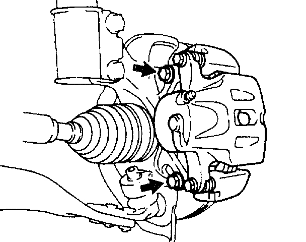
4. SEPARATE FRONT DISC BRAKE CALIPER ASSY LH
a. Remove the 2 bolts, separate the brake caliper from the drive shaft.
5. REMOVE FRONT DISC
Picture 5
6. SEPARATE TIE ROD ASSY LH
a. Remove the cotter pin and nut.
B. Using SST, separate the tie rod end from the steering knuckle.
SST 09628-62011
Picture 6
7. SEPARATE FRONT SUSPENSION ARM SUB-ASSY LOWER NO. 1 LH
a. Remove the bolt and 2 nuts, and separate the lower suspension arm from the lower ball joint.
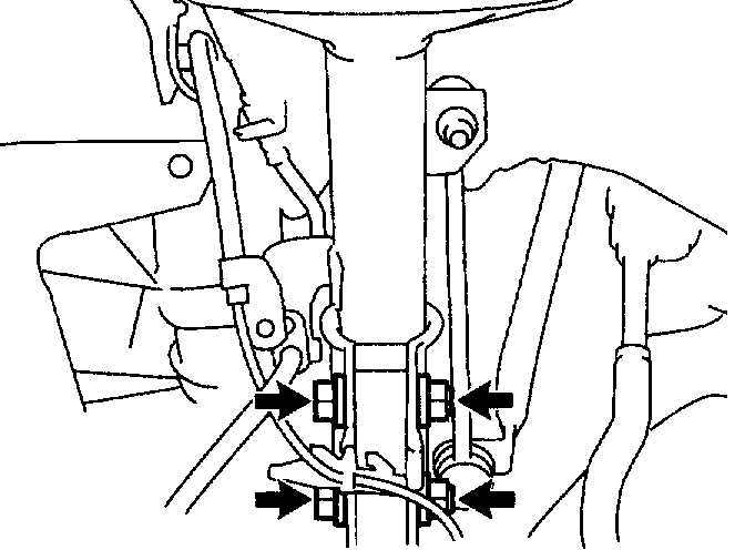
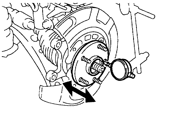
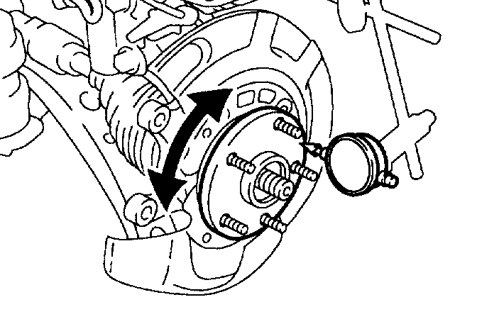
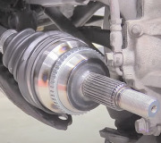
8. REMOVE FRONT AXLE ASSY LH
a. Using a plastic hammer, separate the drive shaft from the axle hub.
NOTICE: Be careful not to damage the boot and ABS speed sensor rotor.
B. Remove the 2 bolts, nuts and steering knuckle with the axle hub.
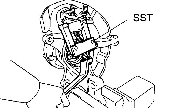
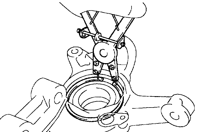
9. REMOVE LOWER BALL JOINT ASSY FRONT LH
Picture 7
a. Remove the cotter pin and nut.
Picture 8
b. Using SST, remove the ball joint.
SST 09628-62011
Picture 9
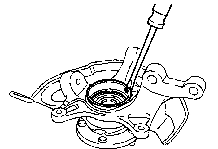
10. REMOVE FRONT WHEEL BEARING DUST DEFLECTOR NO. 1 LH
a. Using a screwdriver, remove the dust deflector.
Picture 10
11. REMOVE FRONT AXLE HUB LH HOLE SNAP RING
a. Using a snap ring plier, remove the snap ring.
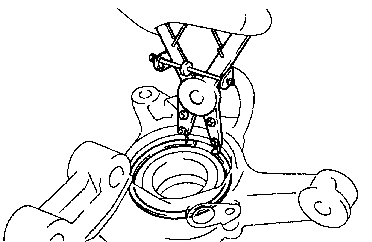
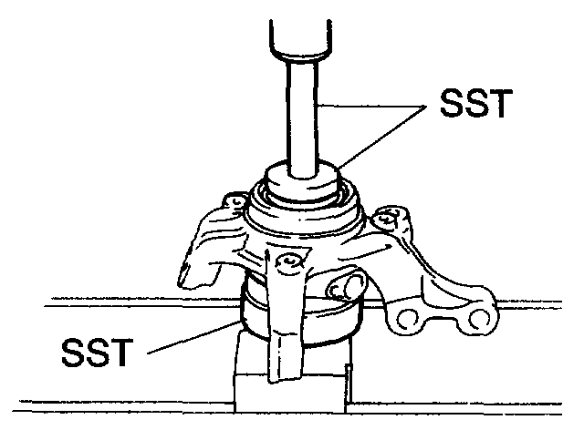
12. REMOVE FRONT AXLE HUB SUB-ASSY LH
Picture 11
a. Using SST, remove the axle hub.
SST 09520-00031
Picture 12
b. Using SST and a press, remove the inner race (outside) from the axle hub.
SST 09950-00020, 09950-60010 (09951-00410), 09950-70010 (09951-07100)
13. REMOVE DISC BRAKE DUST COVER FRONT LH
a. Using a torx wrench (T30), remove the 4 bolts and dust cover.
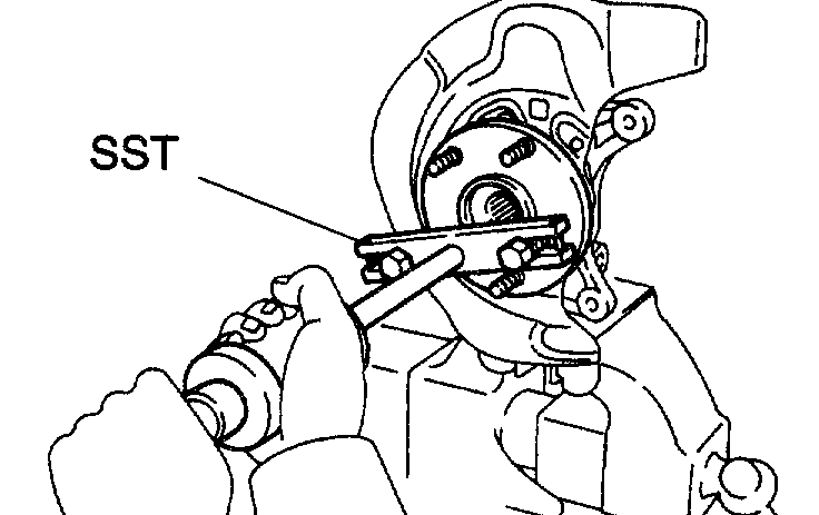
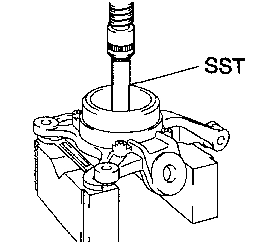
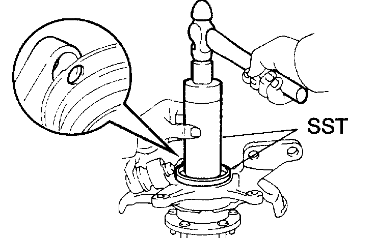
14. REMOVE FRONT AXLE HUB LH BEARING
a. Place the inner race (outside) on the bearing.
Picture 13
b. Using SST and a press, press the bearing until it contacts with the SST.
SST 09527-17011, 09950-60010 (09951-00600), 09950-70010 (09951-07100)
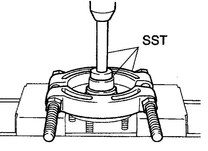
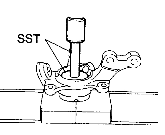
Picture 14
c. Using a spanner to make the steering knuckle horizontal, fix it to the V block as shown in the illustration.
NOTICE: Be sure the steering knuckle is horizontally positioned.
D. Using SST and a press, remove the bearing.
SST 09950-60010 (09951-00600), 09950-70010 (09951-07100)
Picture 15
15. INSTALL FRONT AXLE HUB LH BEARING
a. Using SST and a press, install a new bearing to the steering knuckle.
SST 09950-60020 (09951-00680), 09950-70010 (09951-07100)
16. INSTALL DISC BRAKE DUST COVER FRONT LH
a. Place the dust cover and using a torx wrench (T30), torque the 4 bolts.
Picture 16
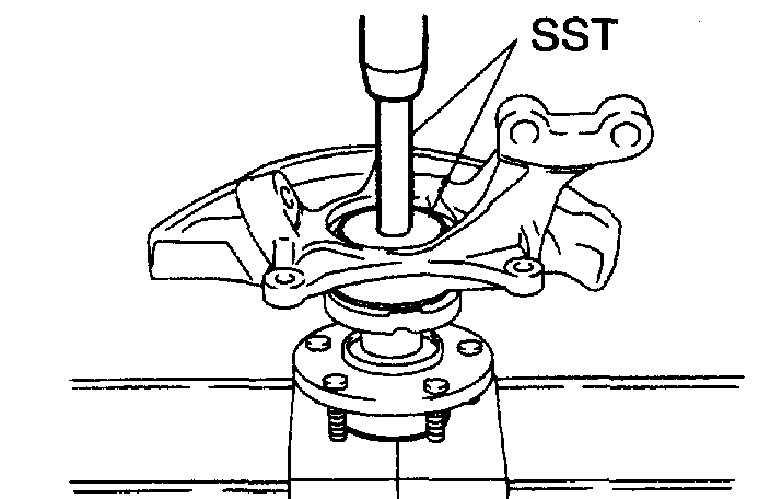
17. INSTALL FRONT AXLE HUB SUB-ASSY LH
a. Using SST and a press, install the axle hub.
SST 09608-32010, 09950-60020 (09951-00680), 09950-70010 (09951-07100)
Picture 17
18. INSTALL FRONT AXLE HUB LH HOLE SNAP RING
a. Using snap ring plier, install a new snap ring.
Picture 18
19. FRONT WHEEL BEARING DUST DEFLECTOR NO. 1 LH
a. Using SST and a hammer, install a new dust deflector.
SST 09316-60011 (09316-00011, 09316-00031), 09608-32010
HINT: Align the holes for the ABS speed sensor in the dust deflector with steering knuckle.
20. INSTALL LOWER BALL JOINT ASSY FRONT LH
a. Install the lower ball joint and tighten the nut.
Torque: 123 Nm (1,250 kgf-cm, 90 ft. Lbs.)
b. Install a new cotter pin.
If the holes for the cotter pin are not aligned, tighten the nut further up to 60°.
Picture 19
21. INSTALL FRONT AXLE ASSY LH
a. Install the 2 bolts, nuts and axle assembly to the shock absorber.
Torque: 210 Nm (2,143 kgf-cm, 155 ft. Lbs.)
HINT: Insert the bolt from the front side of the vehicle and tighten the nut.
B. Push the front axle assy toward the outside of the vehicle, fit the splined part of the drive shaft assy to that of the front axle assy and insert the drive shaft assy into the front axle assy
NOTICE:
Do not push out the front axle assy excessively.
Be careful not to damage the drive shaft outboard joint boot.
Be careful not to damage the speed sensor rotor.
22. INSTALL FRONT SUSPENSION ARM SUB-ASSY LOWER NO. 1 LH
a. Connect the lower arm and ball joint with the 2 nuts and bolt.
Torque: 127 Nm (1,300 kgf-cm, 94 ft. Lbs.)
23. INSTALL TIE ROD ASSY LH
a. Connect the tie rod end to the steering knuckle.
B. Install the nut and a new cotter pin.
Torque: 49 Nm (500 kgf-cm, 36 ft. Lbs.
24. INSTALL FRONT DISC
Picture 20
25. INSTALL FRONT DISC BRAKE CALIPER ASSY LH
a. Install the brake caliper assembly with the 2 bolts to the steering knuckle.
Torque: 106.9 Nm (1,090 kgf-cm, 79 ft. Lbs.)
26. INSTALL FRONT AXLE HUB LH NUT
27. SEPARATE FRONT DISC BRAKE CALIPER ASSY LH
28. REMOVE FRONT DISC
Picture 21
29. INSPECT BEARING BACKLASH
a. Using a dial indicator, check the backlash near the center of the axle hub.
Maximum: 0.05 mm (0.0020 inch)
If the backlash exceeds the maximum, replace the bearing.
Picture 22
30. INSPECT AXLE HUB DEVIATION
a. Using a dial indicator, check the deviation at the surface of the axle hub outside the hub bolt.
Maximum: 0.07 mm (0.0027 inch)
If the backlash exceeds the maximum, replace the axle hub.
31. INSTALL FRONT DISC
Picture 23
32. INSTALL FRONT DISC BRAKE CALIPER ASSY LH
a. Install the brake caliper assy with the 2 bolts to the steering knuckle.
Torque: 106.9 Nm (1,090 kgf-cm, 79 ft. Lbs.)
33. INSTALL SPEED SENSOR FRONT LH
34. INSTALL FRONT AXLE HUB LH NUT
35. INSTALL FRONT WHEEL
Torque: 103 Nm (1,050 kgf-cm, 76 ft. Lbs.)
36. INSPECT AND ADJUST FRONT WHEEL ALIGNMENT
37. CHECK ABS SPEED SENSOR SIGNAL
__________________________________________________________________
I hope this helps.
Let me know if I got it right or if you have other questions.
Take care,
Joe
Images (Click to make bigger)
Friday, February 1st, 2019 AT 1:36 PM