VSC and ABS lights are on

Tiny
NATROWAN
  • MEMBER
  • 2004 TOYOTA 4RUNNER
  • 4.0L
  • 6 CYL
  • 4WD
  • AUTOMATIC
  • 180,000 MILES
VSC track, VSC off and ABS lights are on. Two codes C0200 and C1223. I replaced the wheel sensor and lights are still on. I have driven about five miles since sensor replacement. Nothing has been worked on or modified.
Tuesday, February 6th, 2018 AT 6:23 PM

20 Replies

Tiny
HARRY P
  • MECHANIC
  • 2,293 POSTS
Did you happen to check the wiring to the sensor? I would suggest taking the connector off, and with the key on, engine off, use a multi-meter to make sure that you are getting a good strong twelve volts from the reference wire. And you should get less than 100mv from the ground wire.

Jiggle the wires around a bit while checking them to make sure that it is not an erratic problem. If there is not twelve volts at any point, then trace the wire to see if there is a bare spot or a break somewhere.
Was this
answer
helpful?
Yes
No
+1
Tuesday, February 6th, 2018 AT 7:16 PM
Tiny
NATROWAN
  • MEMBER
  • 9 POSTS
I just now unplugged the short wire harness which runs from where it plugs into the right front wheel speed sensor up to the top area of the inner fender. I unplugged it there at the top because it is easier to see. Using a multi meter set at twenty volts the plug showed 10.80 volts. I did not try to move or wiggle the harness. It is pretty stiff and well secured.
Was this
answer
helpful?
Yes
No
Wednesday, February 7th, 2018 AT 7:42 AM
Tiny
NATROWAN
  • MEMBER
  • 9 POSTS
The two wires are orange and the other is blue. Quite sure they go into a larger black plastic conduit that goes along the front under the top of the radiator frame. That same conduit goes into the bottom of the large black fuse box. I imagine those two wires are one piece all the way to the fuse box and the poor connection is probably at the beginning. Ideas?
Was this
answer
helpful?
Yes
No
Wednesday, February 7th, 2018 AT 8:39 AM
Tiny
HARRY P
  • MECHANIC
  • 2,293 POSTS
Well it is going to be a pain to do, but you might have to find the ABS module, disconnect the wires to it, and use a multi-meter and do a continuity test on each wire until you find the one that goes to the sensor in question. In this case, the front passenger side wheel. While you are at it, make sure that the connector to the module is as clean and tight as you can make it. Replace the wire as necessary. Like I said, a total pain. But it should solve your problem.
Was this
answer
helpful?
Yes
No
Wednesday, February 7th, 2018 AT 7:11 PM
Tiny
NATROWAN
  • MEMBER
  • 9 POSTS
Going back to testing the sensor itself. Now this is a new sensor. The video I watched says put the multi meter on AC. I am testing at the top of inner fender. So there is about two feet of wire loom from where it plugs into the sensor to the plug at top of inner fender. I have the multi-meter set as pictured and get no reading when I spin the wheel. Am I doing something wrong right here?
Was this
answer
helpful?
Yes
No
Thursday, February 8th, 2018 AT 6:31 AM
Tiny
NATROWAN
  • MEMBER
  • 9 POSTS
More background information: When I first took out the speed sensor the bolt was barely tight at all. The sensor itself was easy to take out. Could rust and corrosion cause the sensor to space away from the mounting surface. Could that be why I do not get a reading on the multi-meter?
Was this
answer
helpful?
Yes
No
Thursday, February 8th, 2018 AT 5:36 PM
Tiny
HARRY P
  • MECHANIC
  • 2,293 POSTS
Your meter should be on DC 20, not AC, as your car's electrical system is DC powered. And yes, a bit of rust and a loose connection could cause issues too. Clean up mounting surfaces and make sure everything is tight. Keep us posted.
Was this
answer
helpful?
Yes
No
Thursday, February 8th, 2018 AT 7:23 PM
Tiny
NATROWAN
  • MEMBER
  • 9 POSTS
Here is what I know now. Step one. I cleaned the sensor mounting surface to shiny metal. I put the sensor in and tightened. I attached the meter to the sensor, no harness involved. It was difficult, I could only spin the wheel with one hand. But I got a reading. When the wheel would spin there was reading, wheel stop, reading would go away. Then on to step two. I plugged the harness into the sensor. Then unplugged the harness at the top of inner fender. So now it is testing through about two feet of harness. Look at the pictures. First is the meter attached at top of inner fender. I made sure the probes were not touching. The reading on the meter is what I got when I tested from the top of inner fender. That is testing through about two feet of harness and without spinning anything when I did spin the wheel nothing changed, the reading stayed the same. What do you make of all this?
Was this
answer
helpful?
Yes
No
Saturday, February 10th, 2018 AT 11:59 AM
Tiny
HARRY P
  • MECHANIC
  • 2,293 POSTS
Seems to me that the problem is in the wiring between the ABS module and the inner fender. Could even be the connector there. I would say to replace that positive lead wire all the way to the ABS module if possible, or as close to the module as possible. Which brings us to an area that I am not very good at, interpreting wiring diagrams. I am going to go ahead and post what I have regarding the ABS system here. Hopefully you can interpret it. I think I know what it is saying, but I am not 100% so I do not want to mislead you. I will also see if I can get someone who is better with this area than I am.
Was this
answer
helpful?
Yes
No
Saturday, February 10th, 2018 AT 6:59 PM
Tiny
JIS001
  • MECHANIC
  • 3,408 POSTS
I would recommend you unplug the connector at the ABS/skid control unit and measure continuity as recommended earlier.
At pin #13 which is pink with dvom set to ohms measure that end to the speed sensor connector it should read under 1 ohm. Usually will read 0.7. Do the same on blue wire from pin #14 on ABS/skid control unit side to the other end of blue wire on sensor side.

If you read infinity then there is a break in the wire. With the ABS module and sensor still unplugged, probe the sensor side pink wire then the blue wire and touch the ground with the other lead and make sure there is infinite reading. If you read resistance then you have a short to ground and you will need to trace wire to see where it is rubbing.

Do the same thing but now, touch the positive battery lead. Should read infinite. If you have any other reading then you have a short to power. Last thing plug the sensor back and at the ABS/skid control unit probe pins #13 and #14 and have someone spin the wheel like you were doing your test earlier. If you get a reading then the ABS module is defective.
Was this
answer
helpful?
Yes
No
Saturday, February 10th, 2018 AT 7:41 PM
Tiny
NATROWAN
  • MEMBER
  • 9 POSTS
Okay. I want to be sure we are all on the same page here first. Before I do what you spelled out. The picture I sent of the multi-meter reading.22dcv is from the plug at top of inner fender going to the wheel sensor. That plug is unplugged from the harness which goes to the brake module. That reading is from the short piece of harness that goes down to the wheel sensor. My thought is how can it read any kind of voltage? I do not see how it could get any. Secondly, spinning the wheel did not change the.22 voltage. I have not done it yet but I believe that short piece of harness can come out pretty easy. Then I can check continuity. Thoughts?
Was this
answer
helpful?
Yes
No
Sunday, February 11th, 2018 AT 7:17 AM
Tiny
HARRY P
  • MECHANIC
  • 2,293 POSTS
Oh, I thought it was going to the module. My mistake. Yes check continuity in the same fashion as spelled out above, except from end to end of that wiring and not from one end to the module. Run continuity of both of the wires, and then hook one lead up to the negative post on the battery, and the other to the wires and see if there is any continuity. Be sure to disconnect the sensor first though. Does that make sense to you?
Was this
answer
helpful?
Yes
No
Sunday, February 11th, 2018 AT 11:59 AM
Tiny
JIS001
  • MECHANIC
  • 3,408 POSTS
I found this really cool video on YouTube that really simplifies the testing. That way you check the module and harness at the same time. If you do not have a power probe measure the voltage across the two pins like you would a battery. Here is the link and hopefully it ends up being a wheel bearing fault:

Watch "The easiest way to check a bad Wheel speed sensor" on YouTube.

https://youtu.be/jG18XmUJoNU

Let us know what you find.
Was this
answer
helpful?
Yes
No
Sunday, February 11th, 2018 AT 12:30 PM
Tiny
CARADIODOC
  • MECHANIC
  • 33,738 POSTS
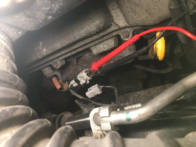
Hi guys. If I followed that correctly, It sounds like you are getting a voltage reading at the sensor's connector, but not at the other end of the two-foot harness that connects to the sensor. What I am interested in first is the resistance reading at the sensor's connector. A typical value that I am familiar with is around 450 - 750 ohms, so I am going to use that for now. JIS001 hit the checks for either wire being shorted to ground and twelve volts, but once you know the resistance value of the sensor, (lets say 500 ohms), plug in the two-foot harness, then recheck the resistance from that point. It should still be 500 ohms. If you find close to 0 ohms, the two wires are shorted together in that two-foot harness. It was also suggested to measure the continuity from the computer. That would also show right away if the two wires were shorted together anywhere, and if continuity is okay.

The little tidbit of value I wanted to add is this type of magnetic sensor develops a positive voltage when a notch in the tone ring approaches the magnet in the sensor, and it generates a negative voltage when the notch moves away from the magnet. As such, it develops an AC sine wave, so measure the signal on the meter's AC volts scale.

The second comment of value has to do with the comment about finding twelve volts feeding one of the wires going to the sensor. When that is done, it can be for two reasons. The first is if that wire becomes grounded, it shorts out that twelve volts, and that is how the computer knows to set a diagnostic fault code related to that wire being grounded. Without that more specific code, all the computer could do is set a code related to the missing signal. That leaves it up to you to narrow down the cause.

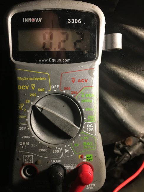
The other reason is speed is a factor in the strength of the signal voltage that is developed. When these sensors develop real low voltages under normal conditions, then they get weaker at low speeds, those signals can drop too low for the computer to detect. To get technical for a moment, it takes 0.6 volts to turn on a standard transistor, then that transistor starts to do its thing, meaning amplify or pass a signal. Once it reaches that 0.6 volt turn-on voltage, it can amplify real tiny voltages of just a few thousandths of a volt. Rather than waiting for vehicle speed to get high enough for the sensor to reach 0.6 volts, they will put a "bias" voltage on the line, in this case, 10.80 volts. That is plenty to turn any transistors on in the computer, then it is a simple matter of watching the tiny voltage changes the sensor generates.

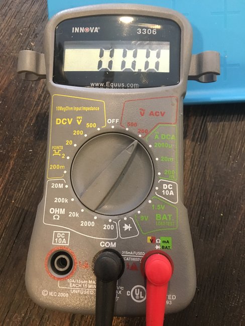
To add to the misery, you might measure that 10.80 volts when the sensor is unplugged, but when connected, the sensor's resistance might draw that voltage down to a more typical six volts. Where this becomes an issue is when taking voltage readings with the sensor plugged in and connected to the computer. On DC volts, you would see the bias voltage of 10.80, (or six volts), but that is supplied by the computer and is not going to change when the wheel is spun. The problem is digital meters take a reading, analyze it, then display it while it takes the next reading. One of those readings might be, lets use my six volts, plus the additional 0.1 volt generated by the sensor. The next reading might get taken when the negative half cycle is generated, so it would see 5.9 volts. The display would bounce around and be somewhat unreadable or at least unsteady. You would be scratching your head trying to understand what the reading means.

When you use the meter on the AC Volts ranges, it automatically blocks the DC component, so in my story, you'd only see the 0.2 volts when spinning the wheel.

For my next great and wondrous comment, on the AC volts ranges, digital meters are only accurate when measuring a 60 Hz sine wave which is house voltage. Some of the more expensive ones are still accurate up to 400 Hz for military use. When the tone ring has only 48 notches or teeth, the wheel has to rotate just over one revolution per second for the meter to be accurate. I am guessing that is about fifteen mph. At other speeds the meter loses its accuracy.

The related issue is wheel speed sensors often do not generate nice clean sine waves. They can generate a positive pulse, then after a short gap, they generate the negative pulse. That starts to look like a square wave pulse, just like when breaker points turn on and off. With a sine wave, current flows one way and increases gradually and smoothly from "0" to maximum positive, then back to "0". From there current goes the other way smoothly from "0" to maximum. Think of the smooth swing back and forth of a grandfather's clock pendulum. With a true square wave, the pendulum is first fully to the left, then instantly fully to the right. Think of how fast the pendulum has to move to get instantly to the other side. That extremely tiny amount of time is the counterpart to the real slow time it took for the signal voltage to rise from "0" to maximum for the sine wave. That is called the "rise time". With the sine wave it is smooth and long. With the square wave, it is extremely fast, and the meter sees that as an extremely high frequency. That could be in the range of many kilocycles, or khz, and that is way too high for the meter to respond to.

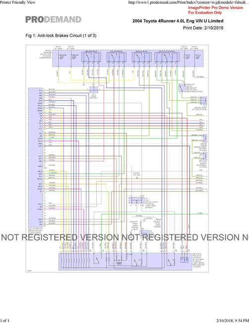
All of this sad story is to explain why a digital voltmeter is not good for getting reliable or accurate readings with wheel speed sensors. They might tell you whether you have something vs. Nothing, but there are too many variables to trust any readings as good or bad. There are two ways to know what is being generated for speed signals. One is to use an oscilloscope used for TV and VCR repair, but not too many mechanics have those. Some engine diagnostic scopes can be rigged up to display those signals, but the time involved is too high. Most problems are diagnosed and solved long before anyone is finished fashioning the test setup. The better way is to let the ABS computer decide whether the signals are okay. It is designed to accept the wide range of frequencies, and the actual voltage is not important. A scanner will show the miles per hour for each wheel, and I suspect there is a place to view the signal voltages. The only value in knowing the voltages would be to compare the readings to each other to see if one is weak. If a signal is weak, that is the time to suspect rust buildup that pushed the sensor away from the tone ring.

Hope this helps make sense of the confusing readings. Will wait to see what the solution is.
Was this
answer
helpful?
Yes
No
Monday, February 12th, 2018 AT 1:52 AM
Tiny
NATROWAN
  • MEMBER
  • 9 POSTS
I believe I have the answer. Such a simple test too. I checked the continuity of both wires of the short harness from the wheel to the top of wheel well. One wire has continuity and one does not. I double checked and it just Is not there. I am going to get that short length of harness. I will post the results.
Was this
answer
helpful?
Yes
No
Monday, February 12th, 2018 AT 7:01 AM
Tiny
KEN L
  • MASTER CERTIFIED MECHANIC
  • 42,878 POSTS
Please let us know what you find. We are interested to see what it is.

Cheers, Ken
Was this
answer
helpful?
Yes
No
Monday, February 12th, 2018 AT 9:39 AM
Tiny
HARRY P
  • MECHANIC
  • 2,293 POSTS
I think you've got it nailed. But do let us know for sure. Its always nice to k know when we successfully help someone figure out such an annoying problem
Was this
answer
helpful?
Yes
No
Tuesday, February 13th, 2018 AT 8:58 AM
Tiny
NATROWAN
  • MEMBER
  • 9 POSTS
Good news guys. Harness arrived at my Toyota dealer this morning. It is exactly as original including the metal mounting brackets. Took about an hour. Requires taking the wheel, right fr off to gain the room needed to replace. I have my own scanner. Didn’t even need to move or drive. Brought up the codes and hit erase and just like that the lights went off. The downfall in all of this is I tested the wheel sensor wrong in the first step. I thought it was bad. That was before I found this forum. I didn’t know each wheel sensor has a short replaceable length of harness. Which of coarse is testable for simple continuity. Thanks for the help. I will keep this forum for future needs for sure.
Was this
answer
helpful?
Yes
No
Wednesday, February 14th, 2018 AT 3:56 PM
Tiny
HARRY P
  • MECHANIC
  • 2,293 POSTS
Hey it's always nice to know when we help someone get their problem fixed!
Was this
answer
helpful?
Yes
No
Wednesday, February 14th, 2018 AT 6:25 PM
Tiny
KEN L
  • MASTER CERTIFIED MECHANIC
  • 42,878 POSTS
It is! Nothing better
Was this
answer
helpful?
Yes
No
Wednesday, February 14th, 2018 AT 8:26 PM

Please login or register to post a reply.

Sponsored links