Dandy. The first thing to be aware of, and this is especially important in this type of circuit, voltage readings are only valid when taken with everything connected and plugged in. This is a little less critical on the 5.0-volt supply wire and the ground wire, but you WILL get a wrong reading on the signal wire. I'll explain that in better detail shortly. If you look at the back of the throttle position sensor's connector, there's a rubber weather seal around each wire. In some cases there's an extra cover that must be removed, but the idea is to stick a voltmeter probe through that seal, alongside the wire. If the probe is too fat, use a stretched-out paper clip to reach the back of the terminal.
First let me explain the fast way to test this circuit. That's to measure the voltage on the signal wire. That's the dark blue wire. If you get the proper results, you're done. That can only happen when the 5.0-volt feed and the ground wires are okay, and the sensor is okay.
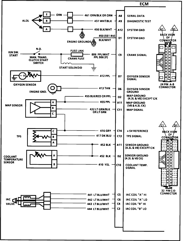
The better way for now is to look at each wire. The first one is the 5.0-volt feed from the Engine Computer. The ignition switch must be in the "run" position. Ground the meter's negative probe to a paint-free point on the engine, body, or the battery's negative post. Back-probe the gray wire. You should find 5.0 volts. Note on the diagram they show that wire also feeding the MAP sensor, so if there's a problem with that wire, you'd have a MAP sensor code too.
Next, measure on the black, ground wire. As a point of interest, it doesn't actually go directly to ground. It goes back to the computer, through some monitoring circuitry, then to ground. That way the computer can monitor that circuit. Due to that circuitry, it is common to find just a little voltage, typically 0.2 volts, on that wire. Don't be thrown if you see that. This ground wire is also used for the coolant temperature sensor. If there's no fault code set for him, that ground wire is most likely okay too.
The secret to setting the code you have is on the signal wire, the dark blue one. This sensor is exactly like the volume control in older tvs and car radios. It's a carbon strip with a movable contact that picks a spot along that strip. The big difference though is this sensor has mechanical stops inside it that limit how far that movable contact can go. It's picking a place somewhere between 0 and 5 volts, but those stops limit it to picking a signal voltage of between 0.5 to 4.5 volts. Those numbers are for training and explanation purposes. In actual practice, you may find 0.42 volts, for example, and 4.37 volts. Those two values are not critical, but the important point is they can't go all the way to 0.0 or 5.0 volts. Those are the two values that trigger fault codes.
You should find something close to 0.5 volts with the throttle closed. Watch the meter as you slowly run the throttle to wide-open-throttle. As you do, the signal voltage should rise smoothly to around 4.5 volts. If that is what you find, the fault code likely set due to the computer seeing a "dropout" or glitch that occurs much too quickly for us to see on a meter. Even readings on expensive scanners don't respond fast enough in most cases. This fault code will also set if you unplug the sensor while the ignition switch is on. When that happens, in most cases the Check Engine light will turn off the next time the ignition switch is turned on after the plug is reconnected, but the fault code will remain in memory. On Chrysler products, if the defect doesn't occur again, the code will self-erase after 50 engine starts. I suspect something similar will occur on GM models. If it doesn't, disconnect the negative battery cable for a couple of minutes.
If you find 5.0 volts on this signal wire, there's either a break between the mating terminals in that connector, or a break inside the sensor. You can test the sensor by doing continuity checks between its three terminals. A faster check is to pop in a different sensor. These have a very low failure rate, so I'd be happy to harvest one from a salvage yard.
If there is a break in that signal wire, logic says you should have 0.0 volts on it, which would set a fault code for "TPS voltage too low". This is where I mentioned you WILL get a wrong reading if you unplug the connector. With a break in that wire / circuit, there's a whole bunch of interconnected circuitry inside the computer that could let some stray voltage "float" to some random value. If that random voltage were to remain between 0.5 and 4.5 volts, the computer will accept it and try to run on it. Engine performance will not be right, but there will be no fault code to tell you where to start the diagnosis. To prevent that, all computer sensor circuits use either a "pull-down" or a "pull-up" resistor. Many import models use pull-down resistors. Those are connected between the signal wire and ground. They are so big electrically that under normal conditions, they have no effect on circuit operation. It's only when there's a break in the signal wire that they drag the voltage down to 0.0 volts. That's outside the acceptable range of 0.5 to 4.5 volts, so a fault code is set.
Most domestic models use pull-up resistors. Those are connected between the signal wire and the internal 5.0-volt supply. Again, they're so high in resistance, they don't affect the circuit until there's a break in the signal wire, then they put 5.0 volts on it to force a defective condition that can be detected. You get the fault code, "TPS voltage too high".
If you get this TPS high code repeatedly or it won't erase, this signal wire is most likely where you'll find the cause. The other possible cause is a break in the sensor's ground wire or a break inside the sensor itself. Remember, the coolant temperature sensor shares this ground circuit, so if it isn't setting a code, the break has to be in the sensor, between its mating pair of terminals in its connector, or in the wire leading up to where the two ground wires are spliced together. All of those are rather rare, so we'll cover that if testing shows that's where we need to go.
There's one last thing we can look at but it requires a scanner or a code reader that can display live data. Some of those are very inexpensive but they usually only work on '96 and newer models. This test is simply to see if your voltmeter shows the same voltage on the signal wire as the scanner shows for TPS voltage. If the voltmeter shows the correct values, between 0.5 and 4.5 volts, but the scanner says the computer is seeing 5.0 volts, there's a break in the signal wire. In this case I'll let you unplug the connector to the TPS, then you should find 0.0 volts on the signal wire. The 5.0 volts the scanner is showing is due to the pull-up resistor, but that 5.0 volts can't make it past the break to get to the meter.
When there is a break in a wire, it is common for whatever caused the damage to affect multiple wires in that area, and there would be additional fault codes or dead circuits. With just the one fault code, the best suspects are the sensor and the connector terminals. Terminals can often be identified by wiggling the connector and seeing the voltage change on the signal wire. Often you can use a pick to bend the terminals to make a tighter connection.
Start with those three voltages and tell me what you find.
Sep 29, 2023 at 11:00 PM