In 2008, the Rav 4 didn't come with a 2.0. It came with a 2.4L. Here are the directions for the removal and replacement of the chain. See if it helps. The attached pics correlate with the directions.
__________________________________________
Here is the removal information. Note that this is a 2.4L
_________________________________________
2008 Toyota Truck RAV4 2WD L4-2.4L (2AZ-FE)
Removal
Vehicle Engine, Cooling and Exhaust Engine Timing Components Timing Chain Service and Repair Removal and Replacement Removal
REMOVAL
2AZ-FE ENGINE MECHANICAL: TIMING CHAIN: REMOVAL
REMOVAL
1. DISCONNECT CABLE FROM NEGATIVE BATTERY TERMINAL
CAUTION: Wait at least 90 seconds after disconnecting the cable from the negative (-) battery terminal to prevent airbag and seat belt pretensioner activation.
2. REMOVE RADIATOR SUPPORT OPENING COVER
3. REMOVE FRONT WHEEL RH
4. REMOVE NO. 1 ENGINE UNDER COVER
5. REMOVE FRONT FENDER APRON RH
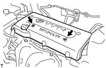
6. REMOVE NO. 1 ENGINE COVER
pic 1
(a)Remove the 2 nuts and cover.
7. DRAIN ENGINE OIL See: Engine Oil > Removal and Replacement > Replacement
8. REMOVE FRONT EXHAUST PIPE See: Exhaust Pipe > Removal and Replacement > Removal
9. REMOVE FRONT SUSPENSION MEMBER REINFORCEMENT RH See: Drive Belt > Removal and Replacement > Removal
10. REMOVE FAN AND GENERATOR V BELT See: Drive Belt > Removal and Replacement > Removal
11. REMOVE GENERATOR ASSEMBLY
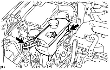
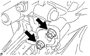
12. REMOVE RADIATOR RESERVOIR
pic 2
(a)Remove the 2 bolts and radiator reservoir.
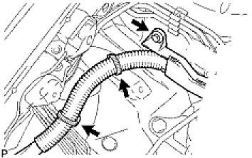
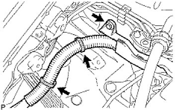
13. REMOVE ENGINE MOUNTING INSULATOR RH
pic 3
(a)Remove the bolt of the wire harness protector.
(b)Disconnect the 2 clamps of the engine wire.
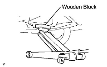
pic 4
(c)Place a transmission jack underneath the engine, then put a wooden block on the jack.
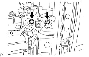
pic 5
(d)Remove the 4 bolts, 2 nuts and engine mounting insulator RH.
NOTE: Do not apply excessive force to the return tube when removing the engine mounting insulator RH.
HINT: Keep clearance by lowering the engine using the transmission jack when removing the engine mounting insulator FR.
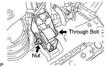
14. REMOVE ENGINE MOUNTING INSULATOR FR
pic 6
(a)Remove the through bolt and nut.
pic 7
(b)Remove the 2 bolts and engine mounting insulator FR.
HINT: Keep clearance by lowering the engine using the transmission jack when removing the engine mounting insulator FR.
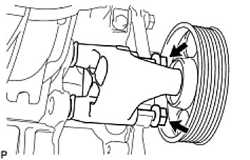
15. REMOVE IDLER PULLEY
pic 8
(a)Loosen the 2 bolts and remove the idler pulley with the 2 bolts.
16. REMOVE IGNITION COIL ASSEMBLY See: Ignition Coil > Removal and Replacement > Removal
17. REMOVE SPARK PLUG See: Valve Clearance > Adjustments > Adjustment
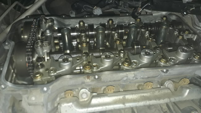
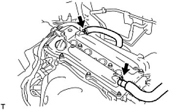
18. REMOVE CYLINDER HEAD COVER SUB-ASSEMBLY
pic 9
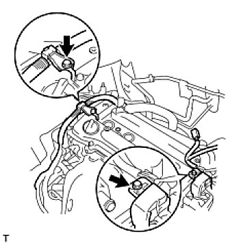
(a)Disconnect the 2 ventilation hoses form the cylinder head cover.
pic 10
(b)Remove the 2 bolts and disconnect the 2 engine wires.
pic 11
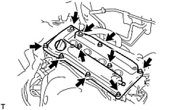
(c)Remove the 8 bolts, 2 nuts and cylinder head cover.
19. REMOVE OIL PAN SUB-ASSEMBLY
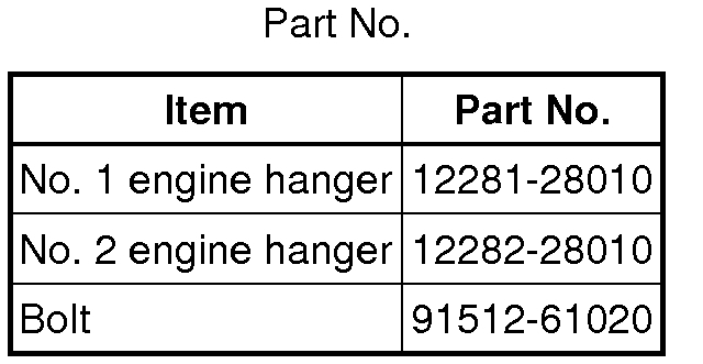
pic 12
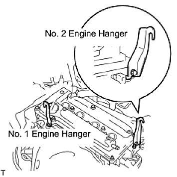
(a)Install the No. 1 and No. 2 engine hangers with the bolts.
Torque: 38 Nm (387 kgf-cm, 28 ft-lbf)
pic 13
(b)Attach the sling device to the engine hangers and chain block.
pic 14
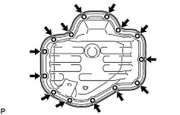
(c)Remove the 12 bolts and 2 nuts.
pic 15
(d)Insert the blade of oil pan seal cutter between the crankcase, chain cover and oil pan, then cut off the applied sealer and remove the oil pan.
NOTE: Be careful not to damage the contact surface of the crankcase, chain cover and oil pan.
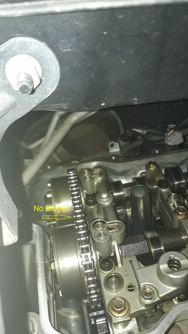
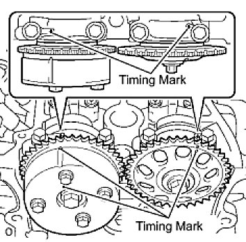
20. SET NO. 1 CYLINDER TO TDC/COMPRESSION
pic 16
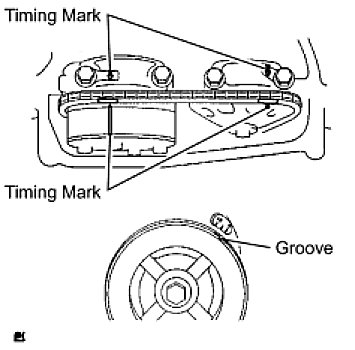
(a)Turn the crankshaft pulley until its groove and the timing mark "0" of the timing chain cover are aligned.
(b)Check that each timing mark of the camshaft timing gear and sprocket is aligned with each timing mark located on the No. 1 and No. 2 bearing caps as shown in the illustration.
If not, turn the crankshaft by 1 revolution (360°) to align the timing marks as above.
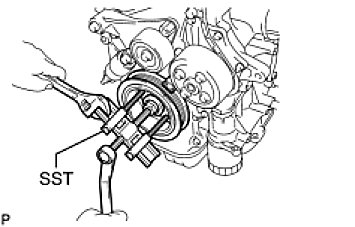
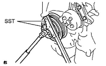
21. REMOVE CRANKSHAFT PULLEY
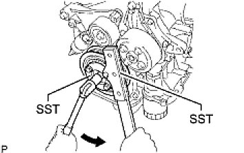
pic 17
(a)Using SST, fix the pulley in place and loosen the pulley bolt.
SST: 09213-54015
91651-60855
SST: 09330-00021
pic 18
(b)Remove the crankshaft pulley.
HINT: If necessary, remove the pulley and pulley bolt using SST.
SST: 09950-50013
09951-05010
09952-05010
09953-05020
09954-05021
SST: 09950-40011
09957-04010
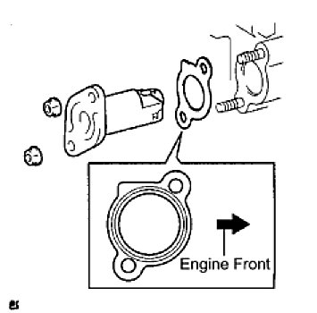
22. REMOVE NO. 1 CHAIN TENSIONER ASSEMBLY
pic 19
(a)Remove the 2 nuts, chain tensioner and gasket.
NOTE: Do not turn the crankshaft without the chain tensioner.
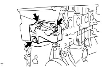
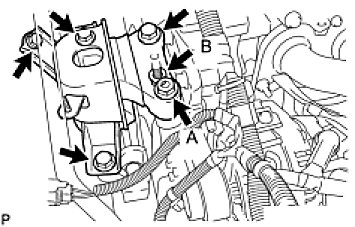
23. REMOVE ENGINE MOUNTING BRACKET RH
pic 20
(a)Remove the 3 bolts and engine mounting bracket RH.
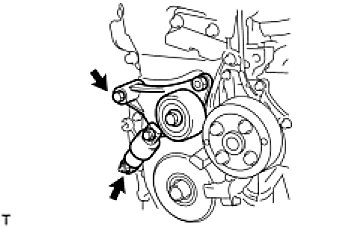
24. REMOVE V-RIBBED BELT TENSIONER ASSEMBLY
(a)Lift the engine upward using the transmission jack.
NOTE: Do not lift the engine more than necessary.
pic 21
(b)Remove the bolt, nut and V-ribbed belt tensioner.
25. REMOVE CRANKSHAFT POSITION SENSOR See: Crankshaft Position Sensor > Removal and Replacement > Removal
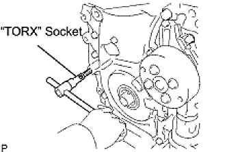
26. REMOVE TIMING CHAIN COVER SUB-ASSEMBLY
pic 23
(a)Using an E10 "TORX" socket, remove the stud bolt for the V-ribbed belt tensioner.
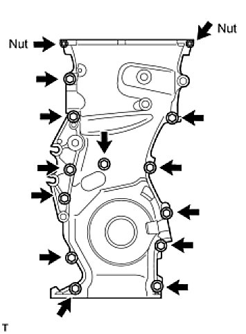
pic 24
(b)Remove the 12 bolts and 2 nuts.
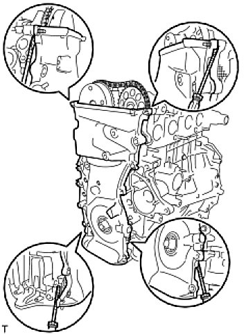
pic 25
(c)Remove the timing chain cover by prying the portions between the timing chain cover, cylinder head and cylinder block with a screwdriver.
NOTE: Be careful not to damage the contact surfaces of the timing chain cover, cylinder head and cylinder block.
pic 26
27. REMOVE NO. 1 CRANKSHAFT POSITION SENSOR PLATE
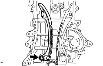
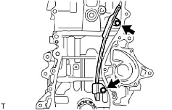
28. REMOVE TIMING CHAIN GUIDE
pic 27
(a)Remove the bolt and timing chain guide.
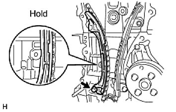
29. REMOVE CHAIN TENSIONER SLIPPER
pic 28
(a)Remove the bolt and chain tensioner slipper.
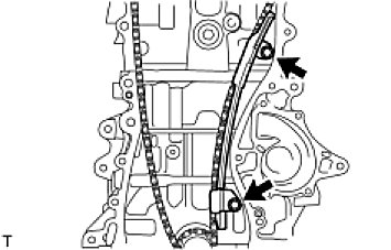
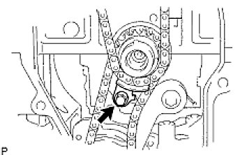
30. REMOVE NO. 1 CHAIN VIBRATION DAMPER
pic 29
(a)Remove the 2 bolts and chain vibration damper.
pic 30
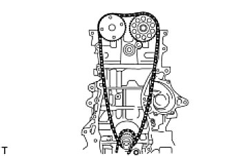
31. REMOVE CHAIN SUB-ASSEMBLY
pic 31
32. REMOVE CRANKSHAFT TIMING SPROCKET
33. REMOVE NO. 2 CHAIN SUB-ASSEMBLY
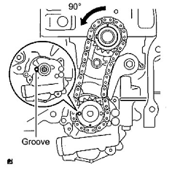
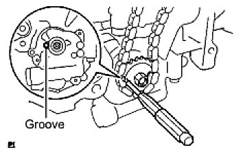
pic 32
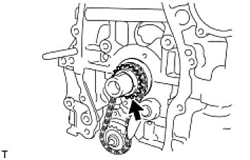
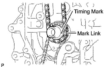
(a)Turn the crankshaft by 90° counterclockwise to align the adjusting hole of the oil pump drive shaft sprocket with the groove of the oil pump.
pic 33
(b)Insert a 4 mm diameter bar into the adjusting hole of the oil pump drive shaft sprocket to lock the gear in position, and then remove the nut.
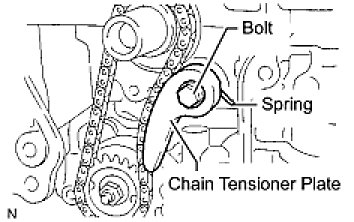
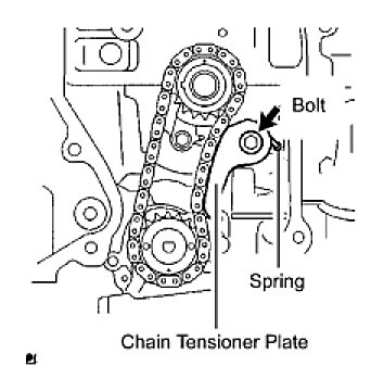
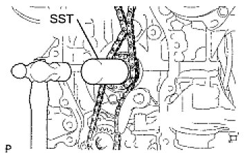
pic 34
(c)Remove the bolt, chain tensioner plate and spring.
(d)Remove the oil pump drive sprocket, oil pump drive shaft sprocket and No. 2 chain.
_________________________________________
Install
2008 Toyota Truck RAV4 2WD L4-2.4L (2AZ-FE)
Installation
Vehicle Engine, Cooling and Exhaust Engine Timing Components Timing Chain Service and Repair Removal and Replacement Installation
INSTALLATION
2AZ-FE ENGINE MECHANICAL: TIMING CHAIN: INSTALLATION
INSTALLATION
1. INSTALL NO. 2 CHAIN SUB-ASSEMBLY
pic 35
(a) Set the crankshaft key in the left horizontal position.
(b) Turn the cutout of the drive shaft so that it faces upward.
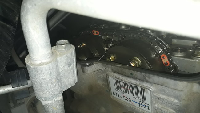
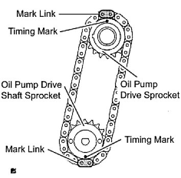
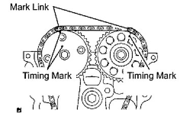
pic 36
(c) Align the yellow mark links with the timing marks of each gear as shown in the illustration.
(d) Install the sprockets onto the crankshaft and oil pump shaft with the chain wrapped on the gears.
(e) Temporarily tighten the oil pump drive shaft sprocket with the nut.
pic 37
(f) Insert the damper spring into the adjusting hole, and then install the chain tensioner plate with the bolt.
Torque: 12 Nm (122 kgf-cm, 9 ft-lbf)
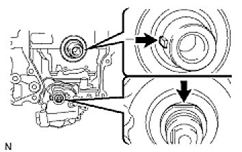
pic 38
(g) Align the adjusting hole of the oil pump drive shaft sprocket with the groove of the oil pump.
(h) Insert a 4 mm diameter bar into the adjusting hole of the oil pump drive shaft gear to lock the gear in position, and then tighten the nut.
Torque: 29.5 Nm (301 kgf-cm, 22 ft-lbf)
pic 39
2. INSTALL CRANKSHAFT TIMING SPROCKET
3. INSTALL NO. 1 CHAIN VIBRATION DAMPER
pic 40
(a) Install the chain vibration damper with the 2 bolts.
Torque: 9.0 Nm (92 kgf-cm, 80 in-lbf)
4. INSTALL CHAIN SUB-ASSEMBLY
pic 41
(a) Set the No. 1 cylinder to TDC/compression.
(1) Turn the camshafts with a wrench (using the hexagonal lobe) to align the timing marks of the camshaft timing gear with each timing mark located on the No. 1 and No. 2 bearing caps as shown in the illustration.
pic 42
(2) Using the crankshaft pulley bolt, turn the crankshaft to position the key on the crankshaft upward.
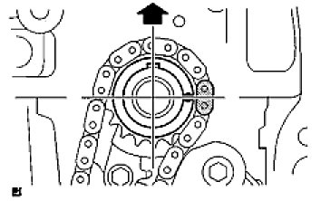
pic 43
(b) Install the chain onto the crankshaft timing sprocket with the gold or orange mark link aligned with the timing mark on the crankshaft.
pic 44
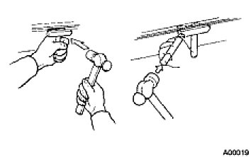
(c) Using SST and a hammer, tap in the crankshaft timing sprocket.
SST: 09309-37010
pic 45
(d) Align the gold or yellow links with each timing mark located on the camshaft timing gear and sprocket, then install the chain.
5. INSTALL CHAIN TENSIONER SLIPPER
pic 46
(a) Install the chain tensioner slipper with the bolt.
Torque: 19 Nm (194 kgf-cm, 14 ft-lbf)
6. INSTALL TIMING CHAIN GUIDE
pic 47
(a) Install the timing chain guide with the bolt.
Torque: 9.0 Nm (92 kgf-cm, 80 in-lbf)
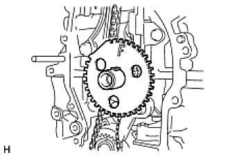
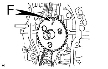
7. INSTALL NO. 1 CRANKSHAFT POSITION SENSOR PLATE
pic 48
(a) Install the sensor plate with the "F" mark facing forward.
8. INSTALL TIMING CHAIN COVER SUB-ASSEMBLY
(a) Remove any old packing material and be careful not to drop any oil on the contact surfaces of the timing chain cover, cylinder head and cylinder block.
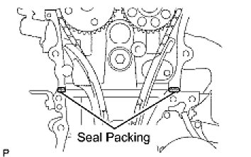
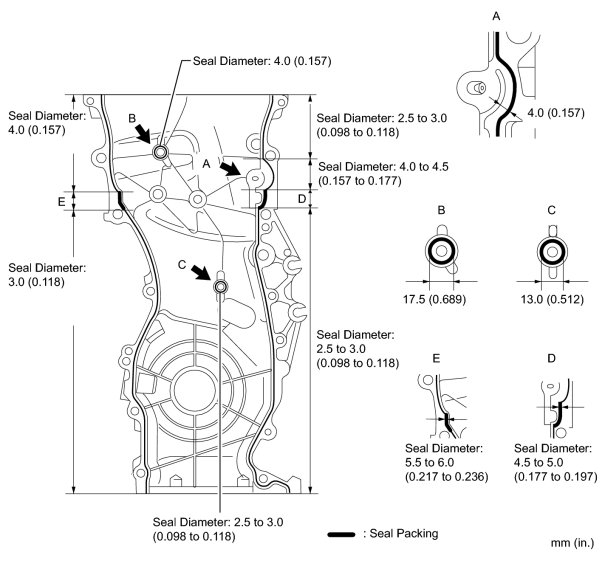
pic 49
(b) Apply seal packing (Diameter 4.0 to 4.5 mm (0.157 to 0.177 in.)) as shown in the illustration.
Seal packing:
Toyota Genuine Seal Packing Black, Three Bond 1207B or equivalent
- Remove any oil from the contact surface.
- Install the chain cover within 3 minutes of applying seal packing.
- Do not add engine oil for at least 2 hours after installing the chain cover.
(c) Apply a continuous bead of seal packing as shown in the illustration.
Seal packing:
Toyota Genuine Seal Packing Black, Three Bond 1207B or equivalent
NOTICE:
- Remove any oil from the contact surface.
- Install the chain cover within 3 minutes of applying seal packing.
- Do not add engine oil for at least 2 hours after installing the chain cover.
pic 50
pic 51
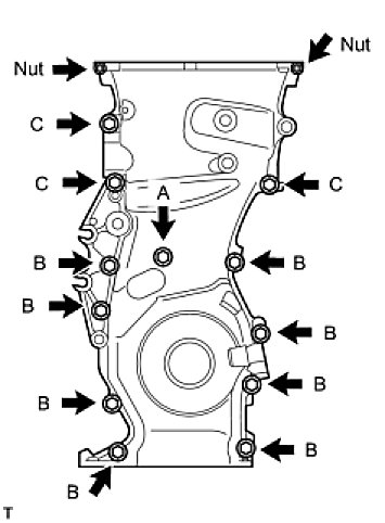
(d) Install the timing chain cover with the 12 bolts and 2 nuts.
Torque Bolt A: 9.0 Nm (92 kgf-cm, 80 in-lbf)
Torque Bolt B: 25 Nm (255 kgf-cm, 18 ft-lbf)
Torque Bolt C: 55 Nm (561 kgf-cm, 41 ft-lbf)
Torque Nut: 11 Nm (112 kgf-cm, 8 ft-lbf)
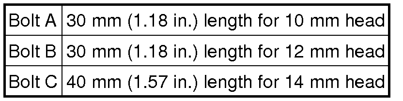
HINT: Bolt length:
pic 52
pic 53
(e) Using an E10 "TORX" socket, install the stud bolt for the V-ribbed belt tensioner.
Torque: 21.5 Nm (219 kgf-cm, 16 ft-lbf)
9. INSTALL NO. 1 CHAIN TENSIONER ASSEMBLY
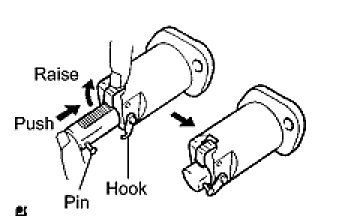
pic 54
(a) Release the ratchet pawl, then fully push in the plunger and hook the hook to the pin so that the plunger is in the position shown in the illustration.
pic 55
(b) Install a new gasket and the chain tensioner with the 2 nuts.
Torque: 9.0 Nm (92 kgf-cm, 80 in-lbf)
NOTE: When installing the chain tensioner, set the hook again if the hook releases the plunger.
10. INSTALL V-RIBBED BELT TENSIONER ASSEMBLY
pic 56
(a) Install the V-ribbed belt tensioner with the bolt and nut.
Torque: 59.5 Nm (607 kgf-cm, 44 ft-lbf)
NOTE: Do not lift the engine more than necessary.
11. INSTALL ENGINE MOUNTING BRACKET RH
pic 57
(a) Install the engine mounting bracket RH with the 3 bolts.
Torque: 55 Nm (561 kgf-cm, 41 ft-lbf)
12. INSTALL CRANKSHAFT PULLEY
pic 58
(a) Using SST, fix the pulley in place and tighten the bolt.
SST: 09213-54015
91651-60855
SST: 09330-00021
Torque: 180 Nm (1,835 kgf-cm, 133 ft-lbf)
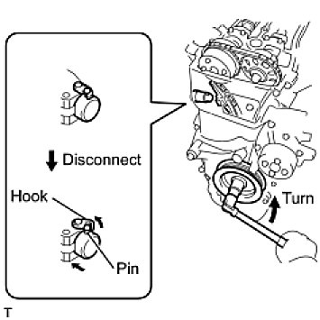
pic 59
(b) Turn the crankshaft counterclockwise, then disconnect the plunger knock pin from the hook.
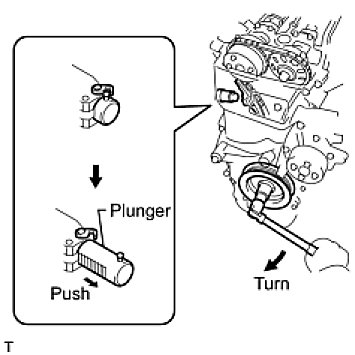
pic 60
(c) Turn the crankshaft clockwise, then check that the plunger is extended.
13. INSTALL OIL PAN SUB-ASSEMBLY
(a) Remove any old packing material and be careful not to drop any oil on the contact surfaces of the cylinder block and oil pan.
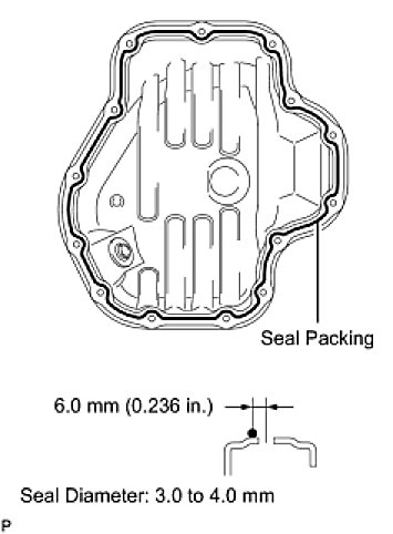
pic 61
(b) Apply a continuous bead of seal packing (Diameter 3.0 to 4.0 mm (0.118 to 0.157 in.)) as shown in the illustration.
Seal packing:
Toyota Genuine Seal Packing Black, Three Bond 1207B or equivalent
- Remove any oil from the contact surface.
- Install the oil pan within 3 minutes of applying seal packing.
- Do not add engine oil for at least 2 hours after installing the oil pan.
(c) Install the oil pan to the cylinder block.
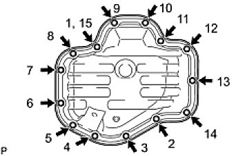
pic 62
(d) Uniformly tighten the 12 bolts and 2 nuts in the sequence shown in the illustration.
Torque: 9.0 Nm (92 kgf-cm, 80 in-lbf)
pic 63
(e) Place a transmission jack underneath the engine, then put a wooden block on the jack.
(f) Remove the chain block and sling device.
(g) Remove the No. 1 and No. 2 engine hangers.
14. INSTALL CRANKSHAFT POSITION SENSOR See: Crankshaft Position Sensor > Removal and Replacement > Installation
15. INSTALL CYLINDER HEAD COVER SUB-ASSEMBLY
(a) Remove any old packing material from the contact surface.
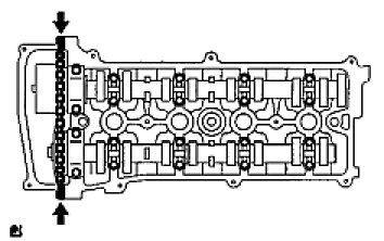
pic 64
(b) Apply seal packing to the 2 locations shown in the illustration.
Seal packing:
Toyota Genuine Seal Packing Black, Three Bond 1207B or equivalent
- Remove any oil from the contact surface.
- Install the oil pan within 3 minutes of applying seal packing.
- Do not add engine oil for at least 2 hours after installing the oil pan.
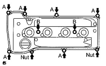
pic 65
(c) Install the cylinder head cover with the 8 bolts and 2 nuts.
Torque Bolt A: 11 Nm (112 kgf-cm, 8 ft-lbf)
Torque Bolt B: 14 Nm (143 kgf-cm, 10 ft-lbf)
Torque Nut: 11 Nm (112 kgf-cm, 8 ft-lbf)
pic 66
(d) Install the 2 engine wires with the 2 bolts.
Torque: 8.4 Nm (86 kgf-cm, 74 in-lbf)
pic 67
(e) Connect the 2 ventilation hoses to the cylinder head cover.
16. INSTALL SPARK PLUG See: Valve Clearance > Adjustments > Adjustment
17. INSTALL IGNITION COIL ASSEMBLY See: Ignition Coil > Removal and Replacement > Installation
18. INSTALL IDLER PULLEY
pic 68
(a) Install the idler pulley with the 2 bolts.
Torque: 60 Nm (612 kgf-cm, 44 ft-lbf)
19. INSTALL ENGINE MOUNTING INSULATOR RH
pic 69
(a) Install the engine mounting insulator RH with the 4 bolts and 2 nuts.
Torque: 95 Nm (969 kgf-cm, 70 ft-lbf)
Torque: 95 Nm (969 kgf-cm, 70 ft-lbf)
Torque: 52 Nm (530 kgf-cm, 38 ft-lbf)
pic 70
(b) Connect the 2 clamps of the engine wire.
(c) Install the wire harness protector with the bolt.
20. INSTALL ENGINE MOUNTING INSULATOR FR
pic 71
(a) Install the engine mounting insulator FR with the 2 bolts.
Torque: 95 Nm (969 kgf-cm, 70 ft-lbf)
pic 72
(b) Install the through bolt and nut.
Torque: 145 Nm (1,479 kgf-cm, 107 ft-lbf)
HINT: Install the bolt which is used to secure the front engine mounting bracket FR.
21. INSTALL RADIATOR RESERVOIR
pic 73
(a) Install the radiator reservoir with the 2 bolts.
Torque: 5.0 Nm (51 kgf-cm, 44 in-lbf)
22. INSTALL GENERATOR ASSEMBLY
23. INSTALL FAN AND GENERATOR V BELT See: Drive Belt > Removal and Replacement > Installation
24. INSTALL FRONT SUSPENSION MEMBER REINFORCEMENT RH See: Drive Belt > Removal and Replacement > Installation
25. INSTALL FRONT EXHAUST PIPE See: Exhaust Pipe > Removal and Replacement > Installation
26. ADD ENGINE OIL See: Engine Oil > Removal and Replacement > Replacement
27. CONNECT CABLE TO NEGATIVE BATTERY TERMINAL
28. INSPECT FOR ENGINE OIL LEAK
29. INSPECT FOR EXHAUST GAS LEAK
30. INSTALL NO. 1 ENGINE COVER
(a) Install the engine cover with the 2 nuts.
Torque: 7.0 Nm (71 kgf-cm, 62 in-lbf)
31. INSTALL FRONT FENDER APRON RH
32. INSTALL NO. 1 ENGINE UNDER COVER
33. INSTALL FRONT WHEEL RH
34. INSTALL RADIATOR SUPPORT OPENING COVER
________________________
I hope this helps. Let me know.
Take care,
Joe
Images (Click to enlarge)
Dec 29, 2020 at 10:20 PM