Good afternoon,
The recommended time is 150,000 to 175,000 miles. Beyond that, you are on borrowed time.
https://www.2carpros.com/articles/how-a-timing-belt-works
Roy
TIMING BELT
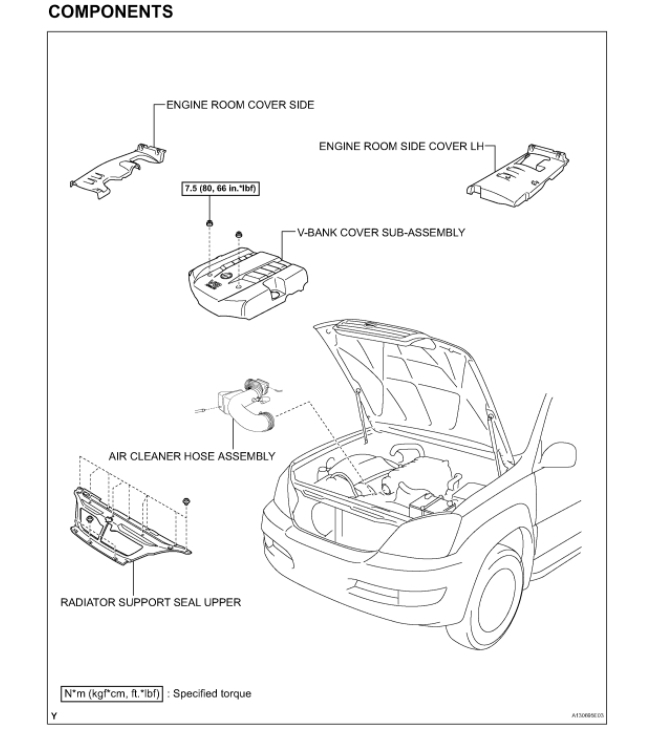
COMPONENTS (Part 1)
imageOpen In New TabZoom/Print
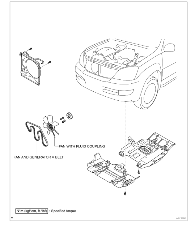
COMPONENTS (Part 2)
imageOpen In New TabZoom/Print
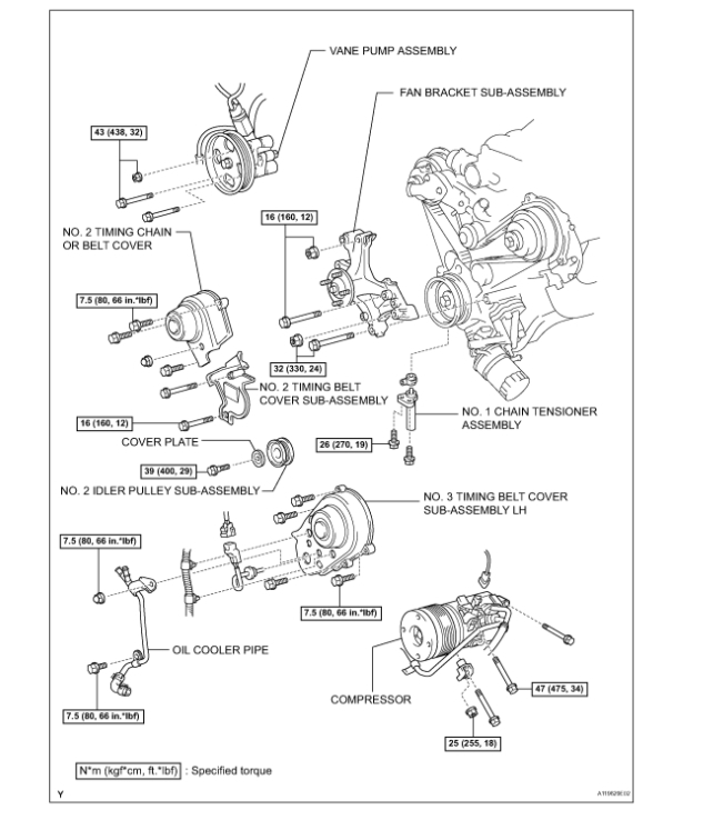
COMPONENTS (Part 3)
imageOpen In New TabZoom/Print
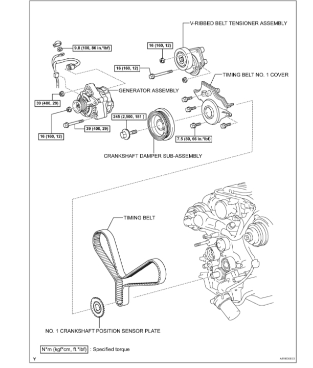
COMPONENTS (Part 4)
imageOpen In New TabZoom/Print
REMOVAL
1. DRAIN ENGINE COOLANT
2. SEPARATE BATTERY NEGATIVE TERMINAL
3. REMOVE V-BANK COVER SUB-ASSEMBLY
(a) Remove the 2 nuts and V-bank cover sub-assembly.
4. REMOVE ENGINE ROOM COVER SIDE
5. REMOVE ENGINE ROOM SIDE COVER LH
6. REMOVE AIR CLEANER HOSE ASSEMBLY
7. REMOVE RADIATOR SUPPORT SEAL UPPER
(a) Remove the 11 clips and radiator support seal upper.
8. REMOVE FAN AND GENERATOR V BELT
imageOpen In New TabZoom/Print
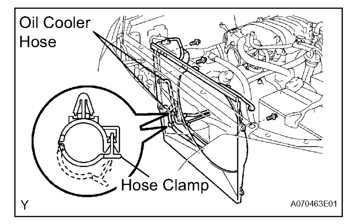
9. REMOVE FAN WITH FLUID COUPLING
(a) Unfasten each clip and the 2 hose clamps, and then separate the 2 oil cooler hoses from the fan shroud.
(b) Remove the 3 bolts and separate the fan shroud from the radiator.
(c) Remove the 4 nuts and separate the fan with fluid coupling from the engine.
(d) Remove the fan shroud and fan with fluid coupling together from the vehicle.
(e) Remove the fan pulley.
imageOpen In New TabZoom/Print
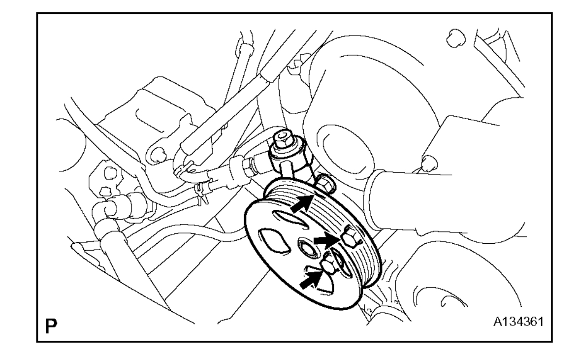
10. SEPARATE VANE PUMP ASSEMBLY
(a) Disconnect the vacuum hose.
(b) Remove the nut, 2 bolts and vane pump assembly.
HINT: Hang up the hoses instead of detaching.
11. REMOVE GENERATOR ASSEMBLY
imageOpen In New TabZoom/Print
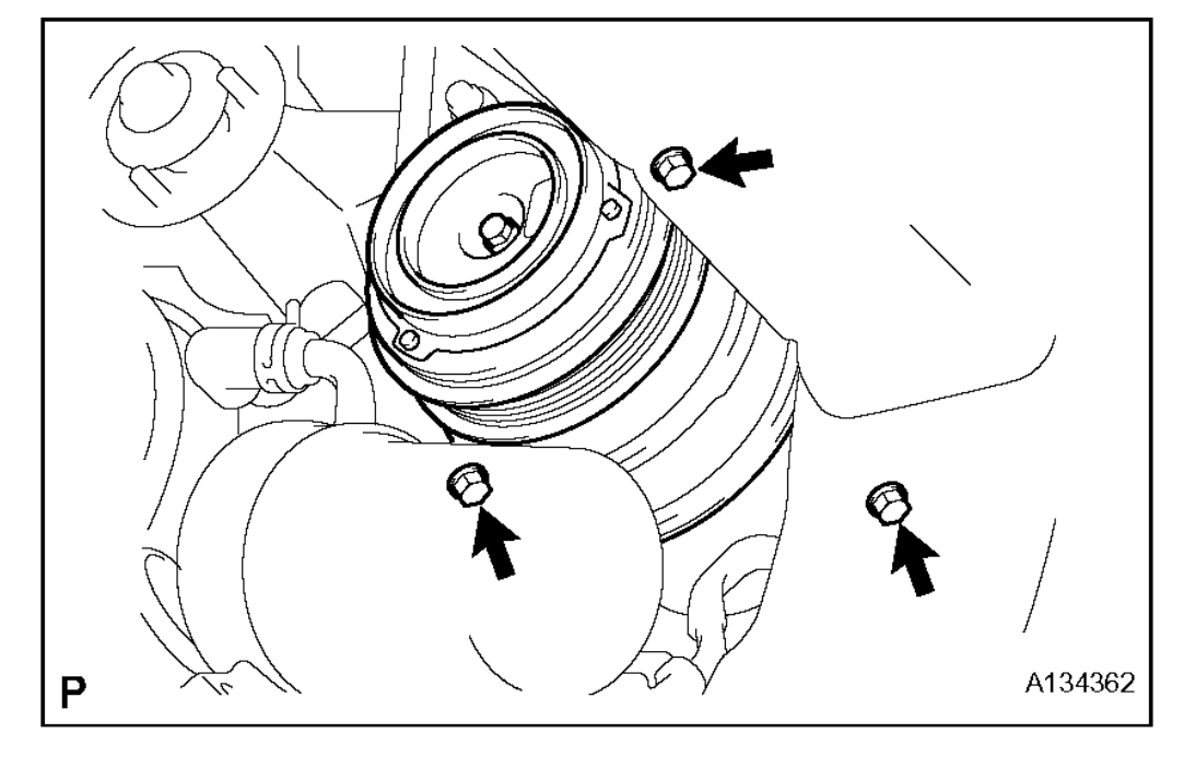
12. SEPARATE COMPRESSOR
(a) Disconnect the compressor connector.
(b) Remove the nut, 3 bolts, compressor stay and compressor.
HINT: Hang up the hoses instead of detaching.
imageOpen In New TabZoom/Print
13. REMOVE NO. 2 IDLER PULLEY SUB-ASSEMBLY
(a) Remove the pulley bolt, cover plate and idler pulley.
14. REMOVE OIL COOLER PIPE
(a) Disconnect the 3 hoses.
(b) Remove the bolt, nut and oil cooler pipe.
imageOpen In New TabZoom/Print
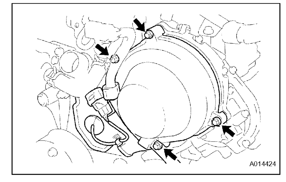
15. REMOVE NO. 3 TIMING BELT COVER SUBASSEMBLY LH
(a) Remove the grommet and separate the cam position sensor connector from the No. 3 timing belt cover sub-assembly LH.
(b) Remove the 4 bolts and No. 3 timing belt cover subassembly LH.
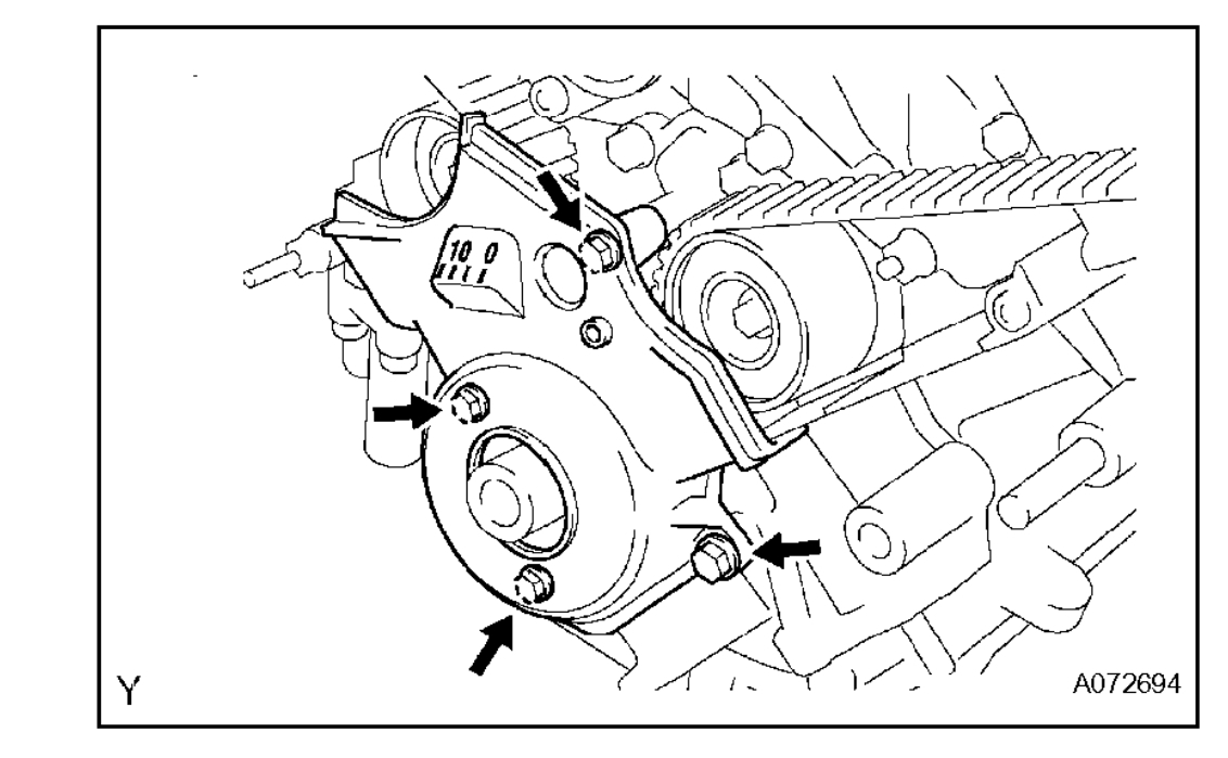
16. REMOVE NO. 2 TIMING CHAIN OR BELT COVER
(a) Remove the nut, 3 bolts and No. 2 timing belt cover.
17. REMOVE NO. 2 TIMING BELT COVER SUBASSEMBLY
(a) Remove the 2 bolts and No. 2 timing belt cover subassembly.
18. REMOVE V-RIBBED BELT TENSIONER ASSEMBLY
(a) Remove the bolt, 2 nuts and V-ribbed belt tensioner.
19. REMOVE FAN BRACKET SUB-ASSEMBLY
(a) Remove the 2 nuts, 2 bolts and fan bracket subassembly.
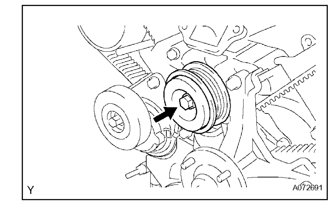
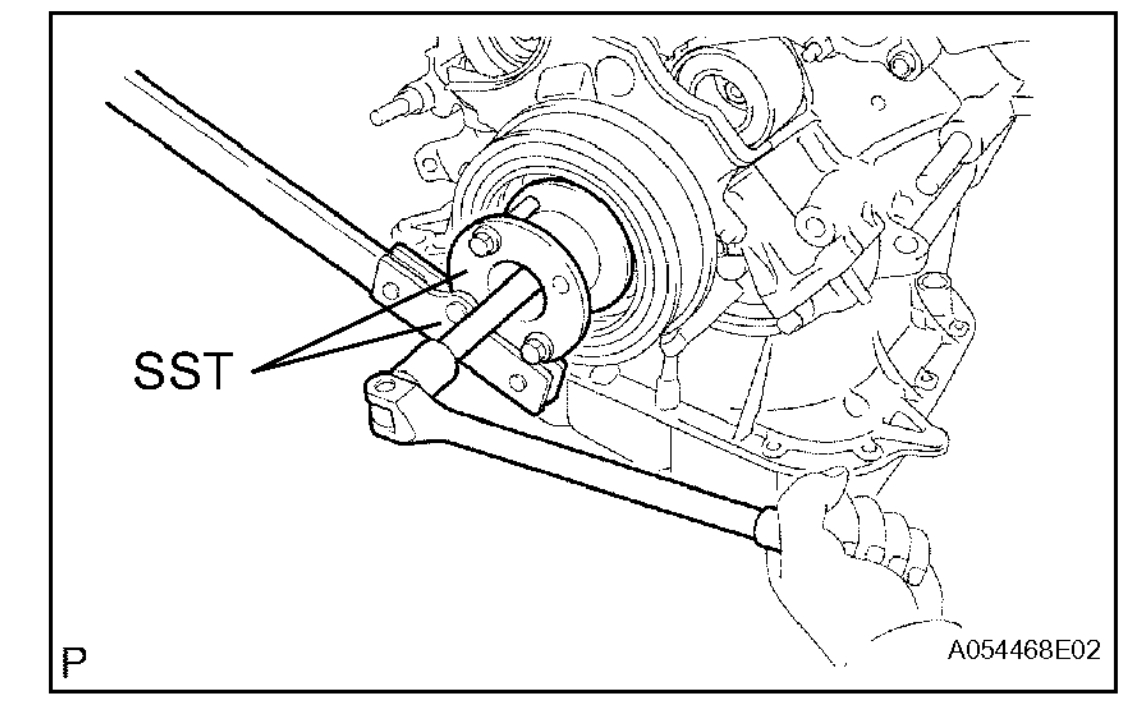
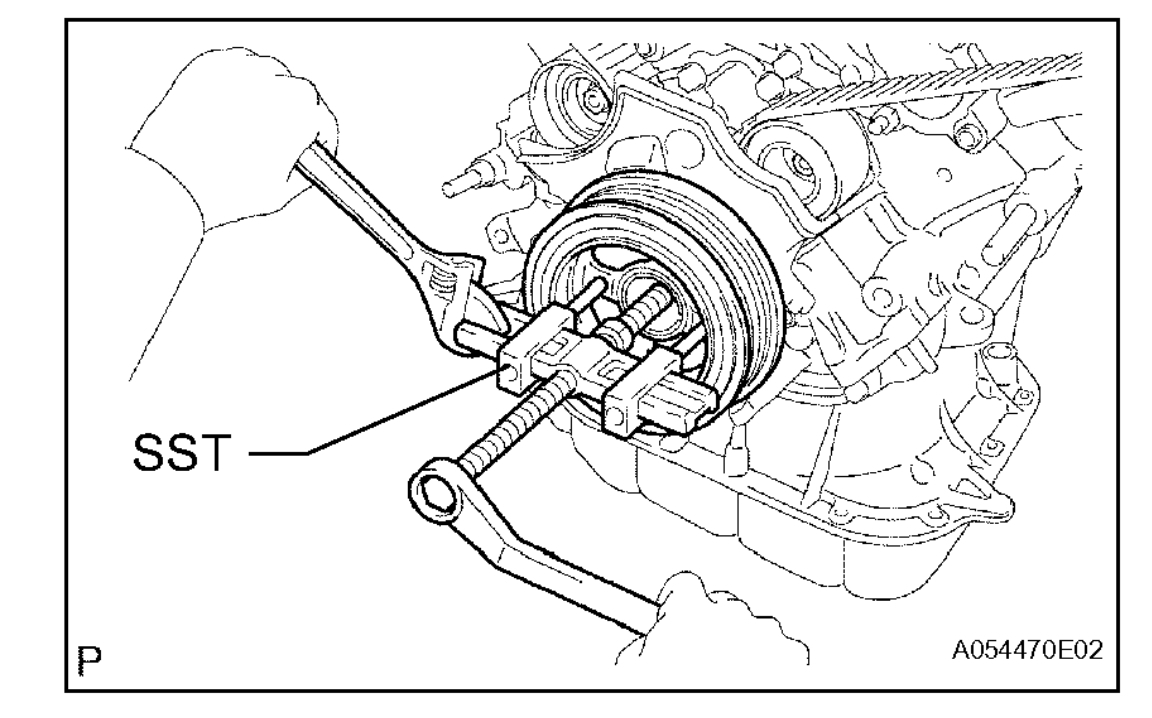
20. REMOVE CRANKSHAFT DAMPER SUB-ASSEMBLY
imageOpen In New TabZoom/Print
(a) Using SST, remove the pulley bolt.
SST 09213-70011 (09213-70020), 09330-00021
imageOpen In New TabZoom/Print
(b) Using SST, remove the crankshaft pulley.
SST 09950-50013 (09951-05010, 09952-05010, 09953-05010, 09953-05020, 09954-05021)
imageOpen In New TabZoom/Print
21. REMOVE TIMING BELT NO. 1 COVER
(a) Remove the 4 bolts and timing belt cover.
imageOpen In New TabZoom/Print
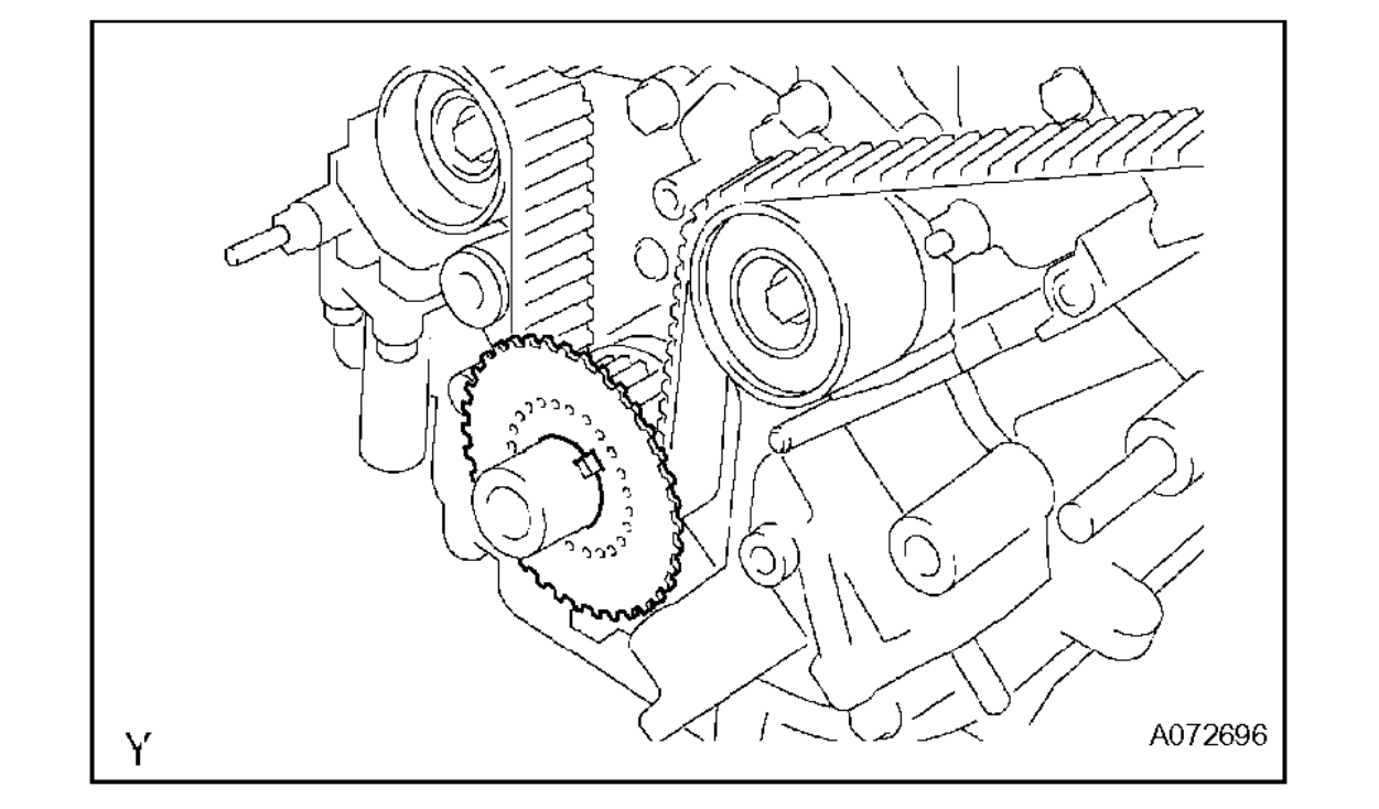
22. REMOVE NO. 1 CRANKSHAFT POSITION SENSOR PLATE
(a) Remove the No. 1 crankshaft position sensor plate.
23. REMOVE TIMING BELT
imageOpen In New TabZoom/Print
(a) If reusing the timing belt, check the installation marks on the timing belt.
(1) Check that there are 3 installation marks on the timing belt by turning the crankshaft as shown in the illustration.
If the installation marks have disappeared, put a new installation mark on the timing belt before removing each part.
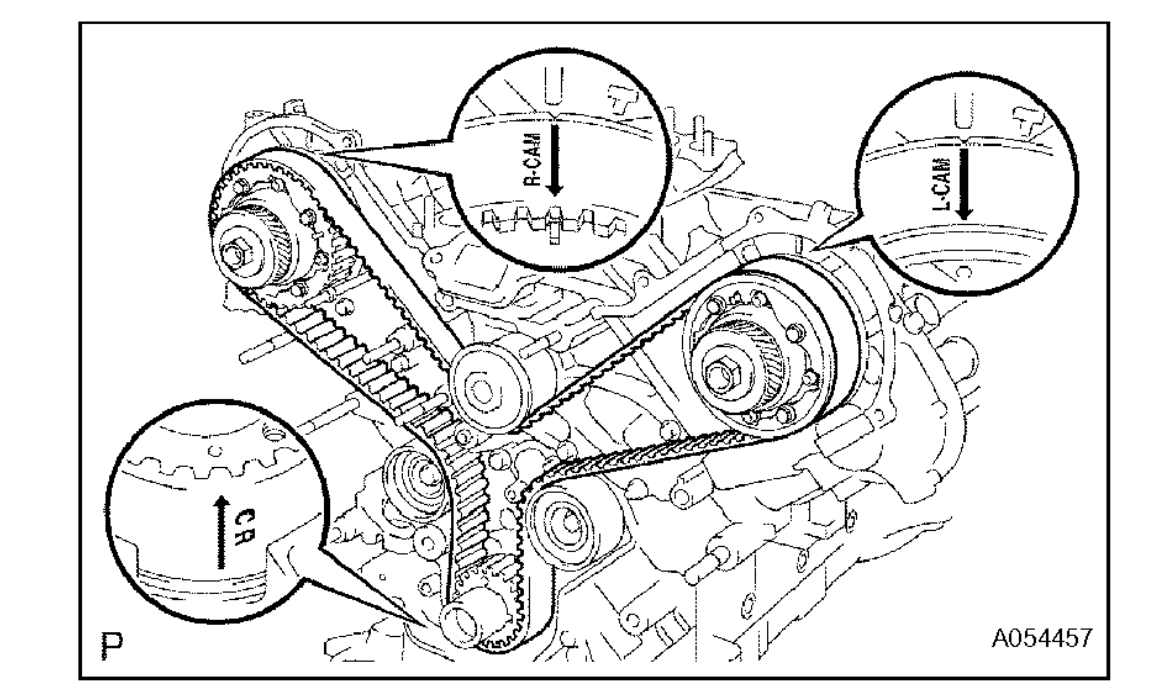
(b) Set the No. 1 cylinder to approximately 50° BTDC/compression.
imageOpen In New TabZoom/Print
(1) Using the crankshaft damper bolt, turn the crankshaft to align the timing marks of the crankshaft timing pulley and oil pump body.
imageOpen In New TabZoom/Print
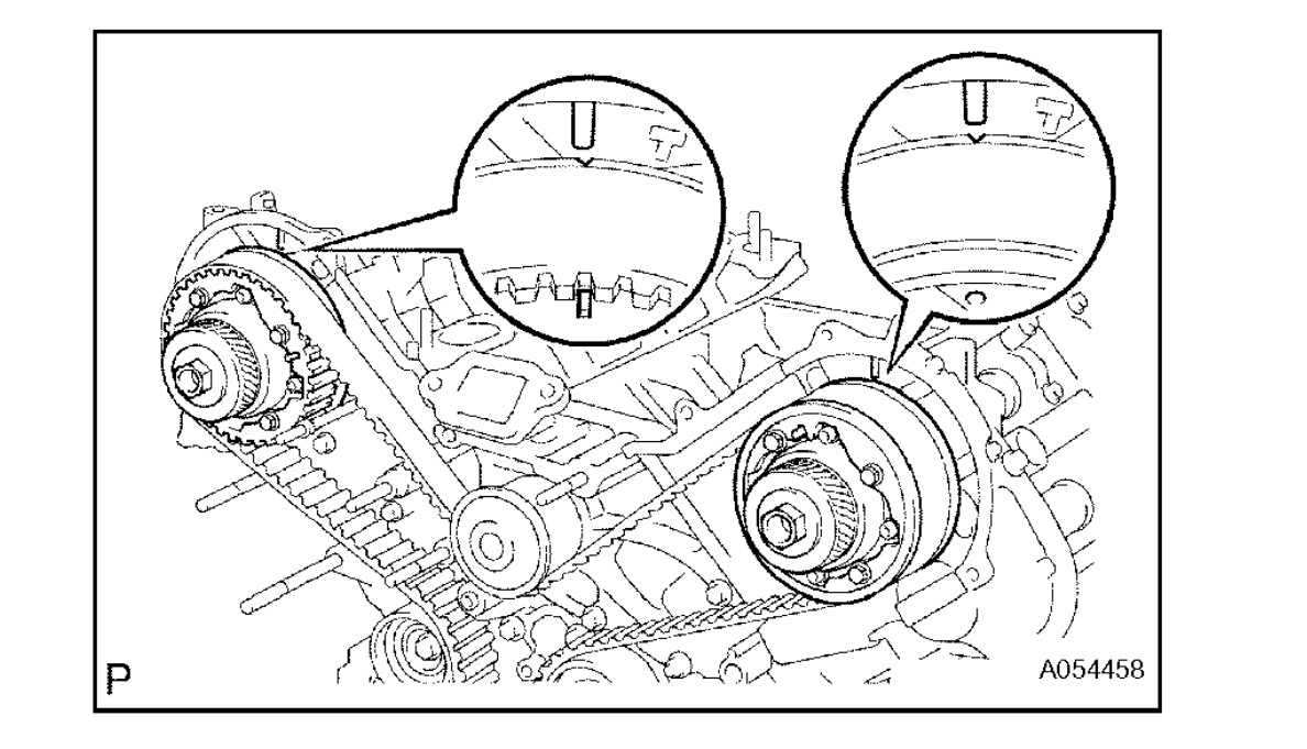
(2) Check that the timing marks of the camshaft timing pulleys and timing belt plates are aligned.
If not, turn the crankshaft 1 complete revolution (360°).
imageOpen In New TabZoom/Print
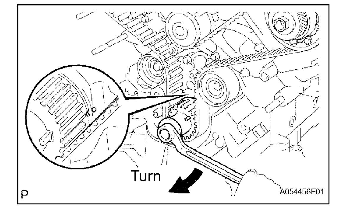
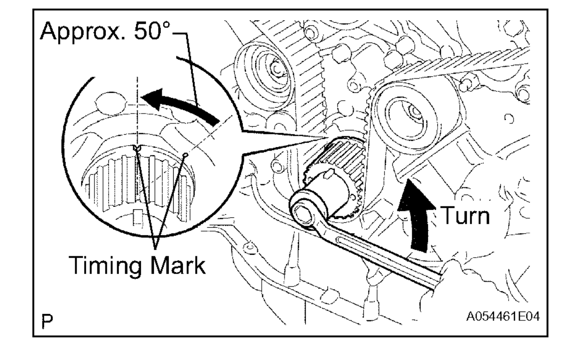
(3) Using the crankshaft damper bolt, turn the crankshaft counterclockwise by approximately 50°.
NOTICE: If the timing belt is disengaged, having the crankshaft pulley at a wrong angle can cause the piston head and valve head to come into contact with each other when removing the camshaft timing pulley and camshaft, causing damage. So always set the crankshaft pulley at the correct angle.
imageOpen In New TabZoom/Print
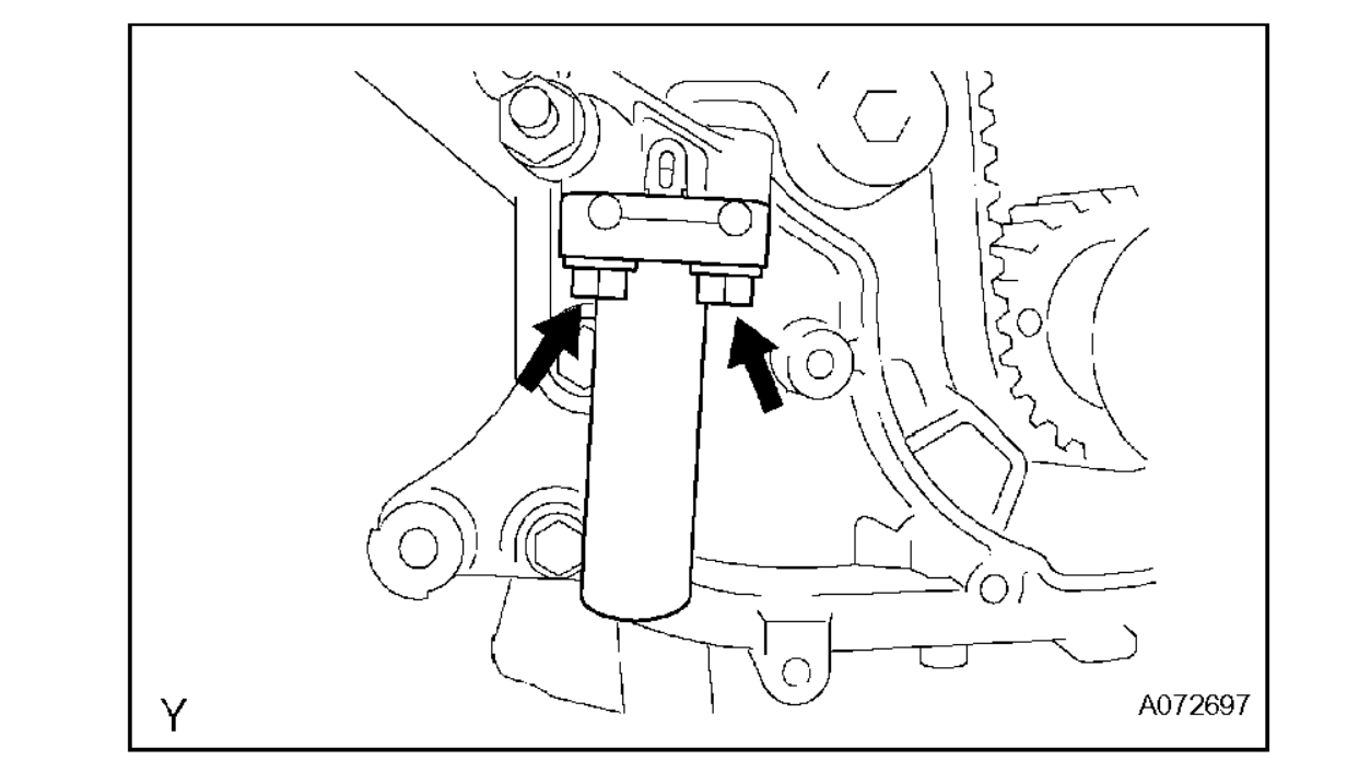
(c) Alternately loosen the 2 bolts, then remove the bolts, the chain tensioner and dust boot.
imageOpen In New TabZoom/Print
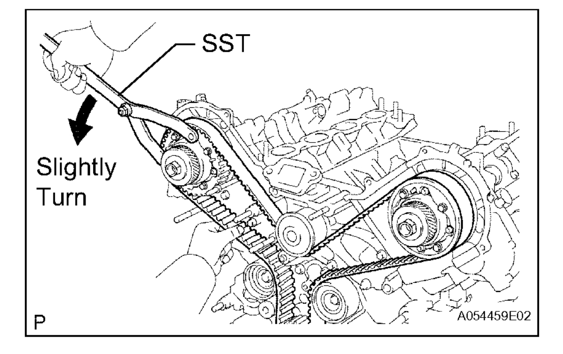
(d) Using a SST, loosen the tension between the camshaft timing pulley (RH bank) and crankshaft timing pulley by turning the camshaft timing pulley (RH bank) counterclockwise slightly.
SST 09960-10010 (09962-01000, 09963-00350)
(e) Disconnect the timing belt from the No. 1 timing belt idler and remove the timing belt.
Images (Click to make bigger)
Monday, March 15th, 2021 AT 1:26 PM