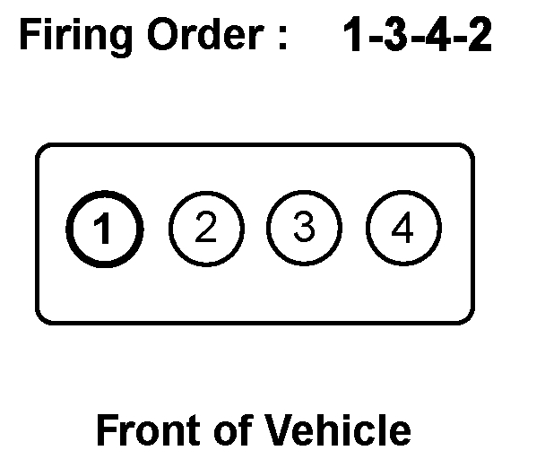
Hi and thanks for using 2CarPros.com The rotor, under the conditions you mentioned, should be pointing at the number one spark plug wire on the distributor cap.
The firing order for this engine is simply 1 2 3 4. See attached picture. Make sure the rotor is facing where the number one spark plug wire is attached,
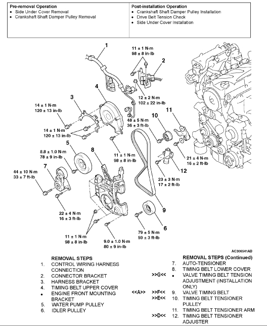
Here are the specific directions for removal and replacement of the belt along with proper timing procedure and pictures for help identifying parts and locations:
TIMING BELT
REMOVAL AND INSTALLATION
REMOVAL SERVICE POINTS
[[A]] VALVE TIMING BELT REMOVAL
CAUTION: Never turn the crankshaft counterclockwise.
Turn the crankshaft clockwise, align each timing mark to set number 1 cylinder to TDC of its compression stroke.
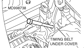
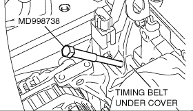
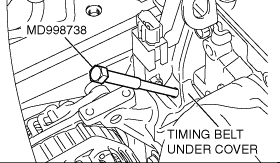
Remove the timing belt under cover rubber plug and then set special tool MD998738.
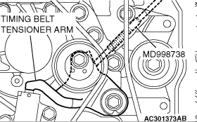
Screw in special tool MD998738 with hands until it contacts the timing belt tensioner arm.
CAUTION: Special tool MD998738 can be gradually installed at a rate of a 30 degree turn per second. If it is screwed in all at once, the timing belt tensioner adjuster rod will not easily retract and special tool MD998738 may bend.
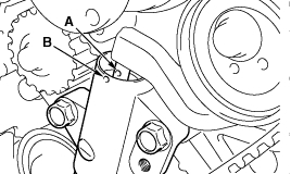
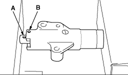
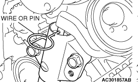
Gradually screw in special tool MD998738 and then align the timing belt tensioner adjuster rod set hole A with the timing belt tensioner adjuster cylinder set hole B.
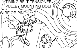
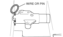
Insert a wire or pin in the set hole aligned.
CAUTION: To reuse the valve timing belt, draw an arrow indicating the rotating direction (clockwise) on the back of the belt using chalk, etc.
After removal of special tool MD998738, loosen the timing belt tensioner pulley mounting bolts and remove the valve timing belt.
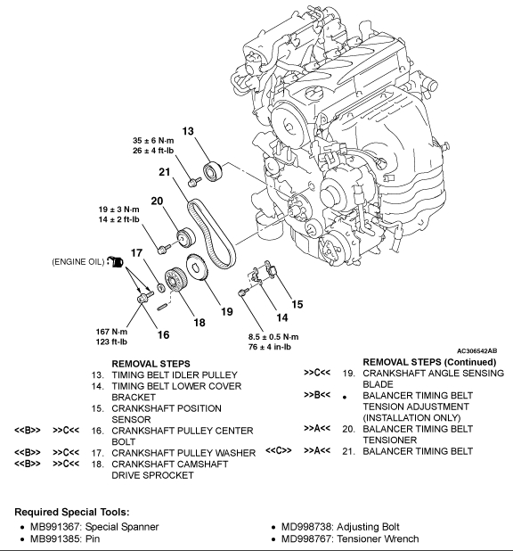
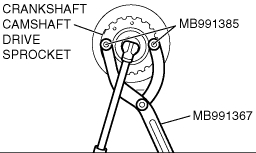
[[B]] CRANKSHAFT PULLEY CENTER BOLT/CRANKSHAFT PULLEY WASHER/CRANKSHAFT CAMSHAFT DRIVE SPROCKET REMOVAL
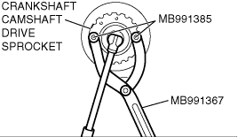
Hold the crankshaft camshaft drive sprocket with special tools MB991367 and MB991385.
Loosen the crankshaft pulley center bolt and remove the crankshaft pulley washer and crankshaft camshaft drive sprocket.
[[C]] BALANCER TIMING BELT REMOVAL
CAUTION: To reuse the balancer timing belt, draw an arrow indicating the rotating direction on the back of the belt using chalk, etc.
INSTALLATION SERVICE POINTS
]]A[[ BALANCER TIMING BELT/BALANCER TIMING BELT TENSIONER INSTALLATION
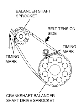
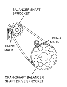
Ensure that the crankshaft balancer shaft drive sprocket timing marks and balancer shaft sprocket timing marks are aligned.
Install the balancer timing belt on the crankshaft balancer shaft drive sprocket and balancer shaft sprocket. There should be no slack on the tension side.
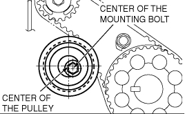
Assemble and temporarily fix the center of the pulley of the balancer timing belt tensioner so that it is at the top left from the center of the assembling bolt, and the pulley flange is at the front-side of the engine.
Adjust the balancer timing belt tension.
]]B[[ BALANCER TIMING BELT TENSION ADJUSTMENT
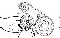
CAUTION: When tightening the mounting bolts, ensure that the tensioner does not rotate with the bolts. Allowing it to rotate with the bolts can cause excessive tension of the belt.
Lift with your fingers the balancer timing belt tensioner in the direction of the arrow. Apply a tensile torque of [3.0 ±0.4 Nm (26 ±4 in. lbs.) ] to the balancer timing belt so the belt is tense without any looseness. Tighten the assembling bolt to the specified torque in this state. Then, fix the balancer timing belt tensioner. Tightening torque: 19 ±3 Nm (14 ±2 ft. lbs.)
Turn the crankshaft clockwise two turns to set number 1 cylinder to TDC of its compression stroke and check that sprocket timing marks are aligned.
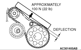
Apply a pressure of approximately 100 N (22 pounds) at the center (arrow area) between the sprocket as shown in the figure, then inspect whether the belt deflection is within the standard value. Standard value:
[When adjusting] 5 - 7 mm (0.20 - 0.27 in.)
[When replacing] 5 - 7 mm (0.20 - 0.27 in.)
If not within the standard value, adjust the belt tension again.
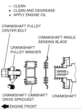
]]C[[ CRANKSHAFT ANGLE SENSING BLADE/CRANKSHAFT CAMSHAFT DRIVE SPROCKET/CRANKSHAFT PULLEY WASHER/CRANKSHAFT PULLEY CENTER BOLT INSTALLATION
Clean or degrease the crankshaft, the crankshaft angle sensing blade, the crankshaft camshaft drive sprocket and crankshaft pulley washer as shown.
NOTE: Also clean the degreased surfaces.
Install the crankshaft angle sensing blade and crankshaft camshaft drive sprocket in the direction shown.
Place the larger chamfer side of the crank shaft pulley washer in the direction shown in the Figure and then assemble on the crank shaft pulley center bolt.
Apply a small of engine oil to the crank shaft pulley center bolt bearing surface and screw.
Hold the crankshaft camshaft drive sprocket with special tools MB991367 and MB991385 in the same manner as removal.
Tighten the crankshaft pulley center bolts to the specified torque. Tightening torque: 167 Nm (123 ft. lbs.)
]]D[[ TIMING BELT TENSIONER ADJUSTER INSTALLATION
Set according to the following procedures when the timing belt tensioner adjuster rod is fully extended.
CAUTION: If the compression is too fast the procedure may damage the rod. Make a point to slowly and thoroughly compress.
Slowly compress the timing belt tensioner adjuster rod using a press or vice, then align the set hole A of the rod with set hole B of the timing belt tensioner adjuster cylinder.
Insert a wire or pin in the set hole aligned.
NOTE: When replacing the timing belt tensioner adjuster with new parts, the timing belt tensioner adjuster is set with a pin.
Install the timing belt tensioner adjuster to the engine and then tighten the mounting bolt to the specified torque. Do not remove the wire or pin until the tension of the valve timing belt is adjusted. Tightening torque: 23 ±3 Nm (17 ±2 ft. lbs.)
]]E[[ TIMING BELT TENSIONER PULLEY INSTALLATION
Temporarily tighten the timing belt tensioner pulley as shown.
]]F[[ VALVE TIMING BELT INSTALLATION
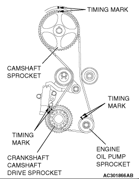
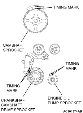
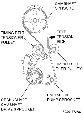
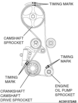
Align the timing marks on the camshaft sprocket, crankshaft camshaft drive sprocket and engine oil pump sprocket.
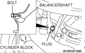
Adjust the timing mark of the engine oil pump sprocket. Unplug the cylinder block plug. Insert a bolt (M6, section width 10 mm, nominal length 45 mm) from the plug hole. If the bolt comes in contact with the balancer shaft, turn the engine oil sprocket one rotation . Re-adjust the timing mark and then check to see that the bolt fits. Do not remove the bolt until the valve timing belt is assembled.
Incorporate the valve timing belt in the following manner so that the tensile force of the belt is not lax.
Place the valve timing belt on the timing belt tensioner pulley and crankshaft camshaft driver sprocket and then support it with your left hand so it does not slide.
Place the valve timing belt on the engine oil pump sprocket while pulling it with the right hand.
Place the valve timing belt on the timing belt idler pulley.
CAUTION: Incorporate the valve timing belt. Then apply reverse rotation (counterclockwise rotation) pressure to the cam shaft sprocket. Re-check to see that each timing mark is aligned while the tension side of the belt is right.
Place the valve timing belt on the camshaft sprocket.
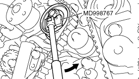
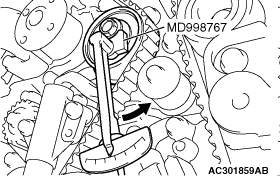
Turn the timing belt tensioner pulley in the direction shown in the figure using special tool MD998767 to apply tension to the valve timing belt. Then temporarily tighten and fix the timing belt tensioner pulley mounting bolt.
Check that the timing marks are aligned.
Remove the bolt inserted in Step 2 above, then assemble the cylinder block plug.
Tighten the cylinder block plug to the specified torque. Tightening torque: 30 ±3 Nm (23 ±2 ft. lbs.)
Adjust the valve timing belt tension.
]]G[[ VALVE TIMING BELT TENSION ADJUSTMENT
Set special tool MD998738 used when removing the valve timing belt.
CAUTION: Always screw in special tool MD998738 in with your hands, since use of a spanner or other tools may damage the wire or pin inserted in the timing belt tensioner adjuster.
Gradually screw in special tool MD998738 to a position in which the wire or pin inserted in the timing belt tensioner adjuster lightly moves.
Turn the crankshaft 1/4 of a revolution in the counterclockwise direction.
Turn the crankshaft in the clockwise direction, align each timing mark to set number 1 cylinder to TDC of its compression stroke.
Loosen the timing belt tensioner pulley mounting bolt.
CAUTION: When tightening the mounting bolt, ensure that the timing belt tensioner pulley does not rotate with the bolt. Allowing it to rotate with the bolt can cause deficient tension of the belt.
With special tool MD998767 and torque wrench, apply tension torque [3.5 Nm (31 in. lbs.) ] to the valve timing belt, and tighten the timing belt tensioner pulley mounting bolt to the specified torque. Tightening torque: 48 ±5 Nm (36 ±3 ft. lbs.)
Remove wire or pin inserted to timing belt tensioner adjuster.
Remove special tool MD998738, and install the rubber plug to the timing belt under cover.
Rotate crankshaft clockwise two turns , and leave it for about15 minutes .
Insert wire or pin removed in Step 7 again, and ensure that it can be pulled out with a light load. When wire or pin can be lightly removed, appropriate tension is applied on timing belt. In this case, remove wire or pin.
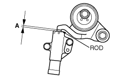
Also the projection of timing belt tensioner adjuster rod (A) is within the standard value, appropriate tension is applied.
Standard value (A): 3.8 - 4.5 mm (0.15 - 0.17 in.)
If wire or pin cannot be easily pulled out, repeat Step 1 through Step 9 to reach proper valve timing belt tension.
CAUTION: Always check the tightening torque of the crank shaft pulley center bolt when turning the crank shaft pulley center bolt counterclockwise. Re-tighten if it is loose.
Check again that the timing marks on sprockets are aligned.
INSPECTION
TIMING BELT TENSIONER ADJUSTER CHECK
Check for oil leak from seal, and replace it if leak is detected.
Check for wear or damage at the top of the rod. Replace it, if required.
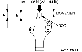
Hold the timing belt tensioner adjuster by hand, and press top end of the rod onto the metal (e.g. cylinder block) under a pressure of 98 - 196 N (22 - 44 pounds) to measure the movement of the rod. Standard value: Within 1 mm (0.039 in.)
A: Length when it is free (not pressed)
B: Length when it is pressed
A - B: Movement
If the measured value is out of the standard value, replace the timing belt tensioner adjuster.
BALANCER TIMING BELT TENSION CHECK
Check the balancer timing belt tension in the following procedures.
Apply a pressure of approximately 100 N (22 pounds) at the center (arrow area) between the sprocket as shown in the figure, then inspect whether the flexure is within the standard value. Standard value: 5 - 10 mm (0.20 - 0.39 in.)
If not within the standard value, adjust the belt tension.
__________________________________________________________________________
Pictures 2 through 34 all correlate with the aforementioned directions.
I do not know if you needed the directions, but thought I would add them for you so you can check your work if needed.
Let me know if you have other questions.
Take care,
Joe
Images (Click to enlarge)
Jun 1, 2018 at 10:01 PM