Hi,
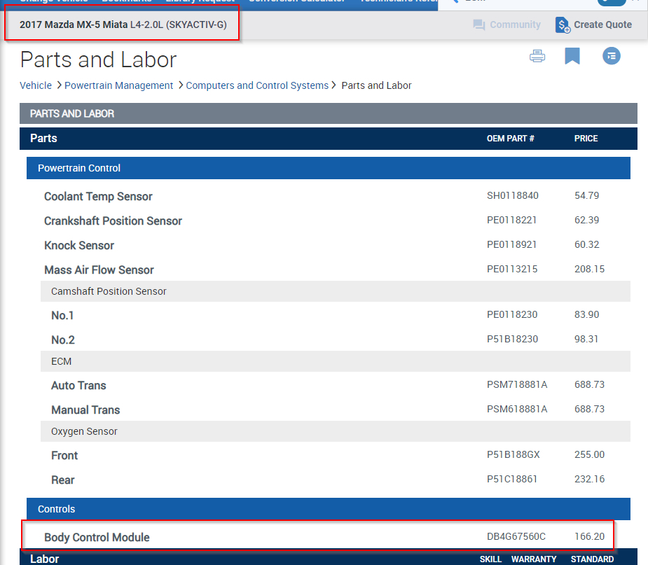
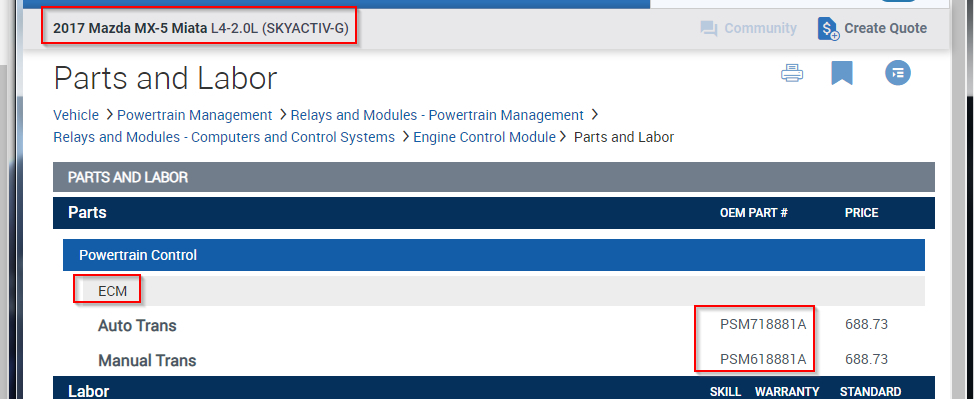
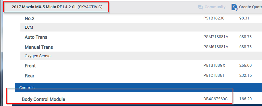
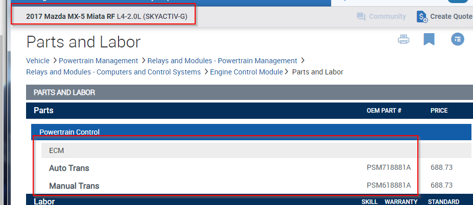
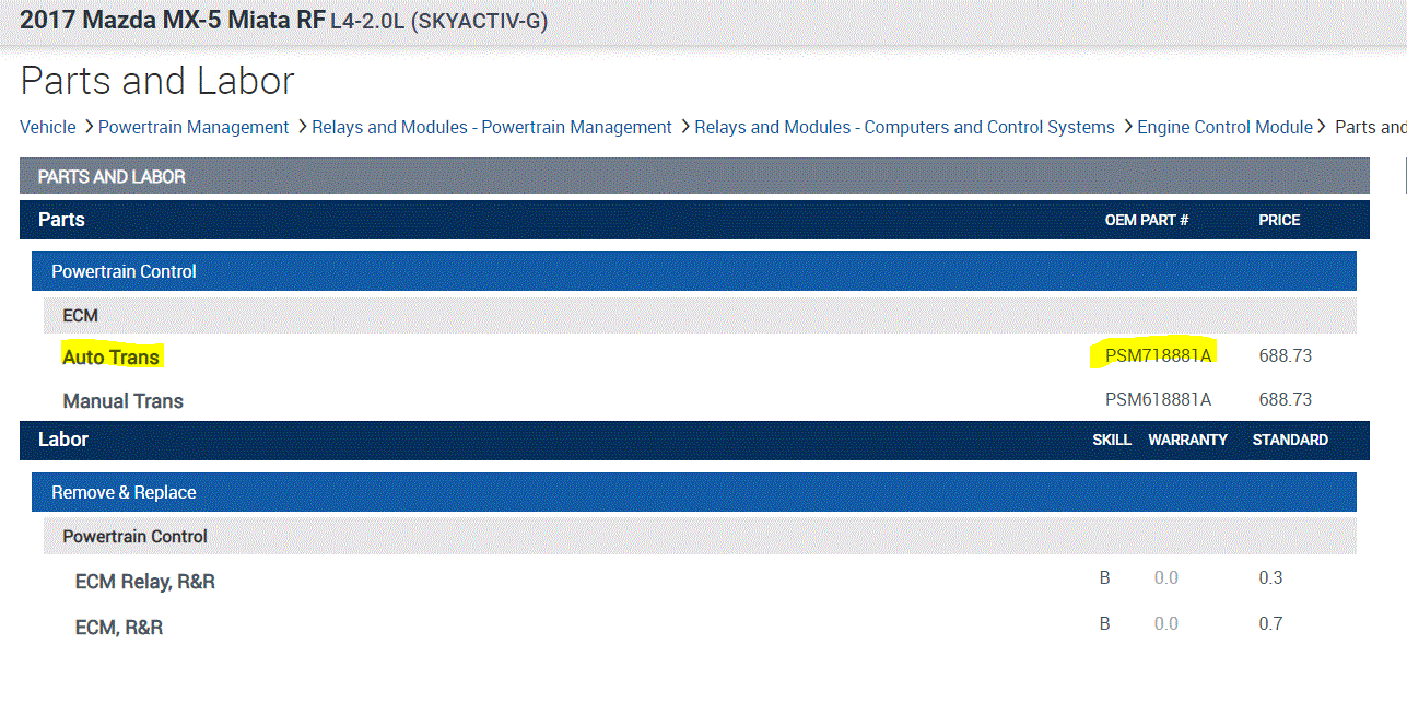
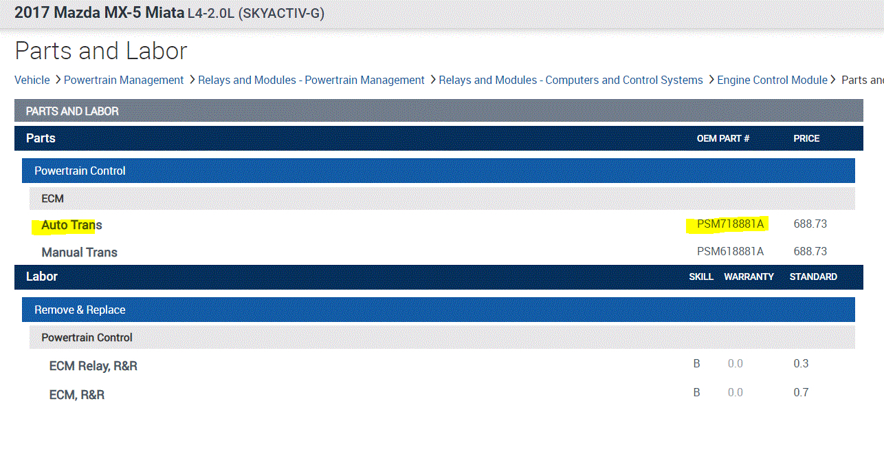
I looked up the part numbers for both. They are listed as the same part. If you look at pic 1 below, it is for the RF model. The second is soft top.
I don't know if you need them, but here are the directions for removal and replacement. The remaining pics below correlate with the directions.
______________________________________________
2017 Mazda MX-5 Miata L4-2.0L (SKYACTIV-G)
PCM REMOVAL/INSTALLATION
Vehicle Powertrain Management Relays and Modules - Powertrain Management Relays and Modules - Computers and Control Systems Engine Control Module Service and Repair Removal and Replacement PCM REMOVAL/INSTALLATION
PCM REMOVAL/INSTALLATION
PCM REMOVAL/INSTALLATION [SKYACTIV-G 2.0]
SM1358095
id0140f4802400
Caution
• If configuration and reprogramming is not performed when the PCM is replaced with a new one, the vehicle specification information and PCM software is not stored in the PCM and the system will not operate normally.
• When performing configuration and reprogramming, it is necessary to read the vehicle specification information from the PCM before replacing it. Connect the M-MDS to the vehicle and perform vehicle identification before removing the PCM. The vehicle specification information is temporarily stored in the M-MDS.
Note
• The PCM prior to replacement stores the vehicle specification information.
• A new PCM does not store any vehicle specification information.
• If the vehicle specification information PCM prior to replacement cannot be read, perform the configuration using As-Built data.
1.Disconnect the negative battery cable. (See NEGATIVE BATTERY CABLE DISCONNECTION/CONNECTION .)
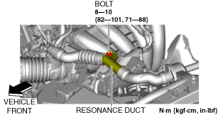
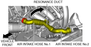
2.Set the resonance duct and air intake hoses No.1 and 2 aside as a single unit using the following procedure. (With resonance chamber No.2)
(1)Remove the bolt shown in the figure.
pic 3
amxuuw00005618
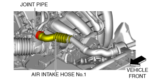
(2)Disconnect the air intake hose No.1 from the joint pipe.
pic 4
amxuuw00005619
(3)Set the resonance duct and air intake hoses No.1 and 2 aside as a single unit in the direction of the arrow shown in the figure.
pic 5
amxuuw00005620
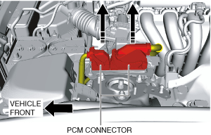
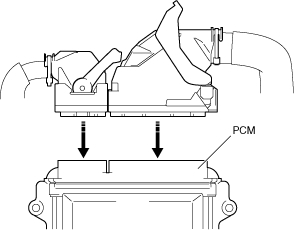
3.Disconnect the PCM connector. (See PCM CONNECTOR CONNECTION NOTE .)
pic 6
amxuuw00003657
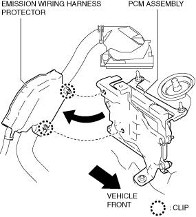
4.Detach the clips and remove the emission wiring harness protector.
pic 7
amxuuw00003658
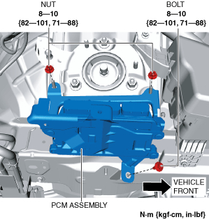
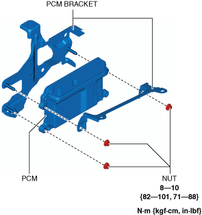
5.Remove the nuts and bolt.
pic 8
amxuuw00003659
6.Remove the PCM assembly.
7.Remove the nuts.
pic 9
amxuuw00003660
8.Remove the PCM from the PCM bracket.
9.Install in the reverse order of removal.
10.When replacing the PCM on the vehicles, perform the following:
Note
• If configuration cannot be performed by reading/writing of the vehicle specification information, perform the configuration using As-Built information after replacing the PCM. (See PCM CONFIGURATION (USING AS-BUILT DATA) [SKYACTIV-G 2.0] .)
(1) Perform the PCM configuration. (See PCM CONFIGURATION (USING READ/WRITE FUNCTION) [SKYACTIV-G 2.0] .)
(2) Perform the immobilizer system-related part programming. (See IMMOBILIZER SYSTEM-RELATED PARTS PROGRAMMING .)
PCM Connector Connection Note
Caution
• Do not touch the PCM connector terminal. The terminal is extremely thin and can be damaged by touching it.
• If the PCM connector is inserted at an angle and the lever is moved, the connector could be damaged. Verify that the PCM connector is inserted straight.
pic 10
amxuuw00003661
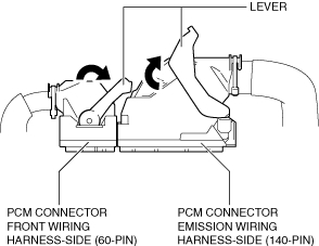
1.Set the PCM connector to the position shown in the figure.
pic 11
amxuuw00003662
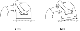
2.Align the PCM connector straight against the connection surface.
pic 12
amxuuw00003663
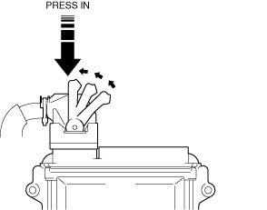
3.Insert the PCM connector straight and press it in until the lever moves up naturally. (Front wiring harness-side connector)
pic 13
amxuuw00003664
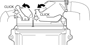
4.Press the PCM connector lever until a click sound is heard.
pic 14
amxuuw00003665
________________________________________
I hope this helps. Let me know if you have other questions.
Take care and God Bless,
Joe
Images (Click to enlarge)
Mar 15, 2021 at 7:37 PM