Hi,
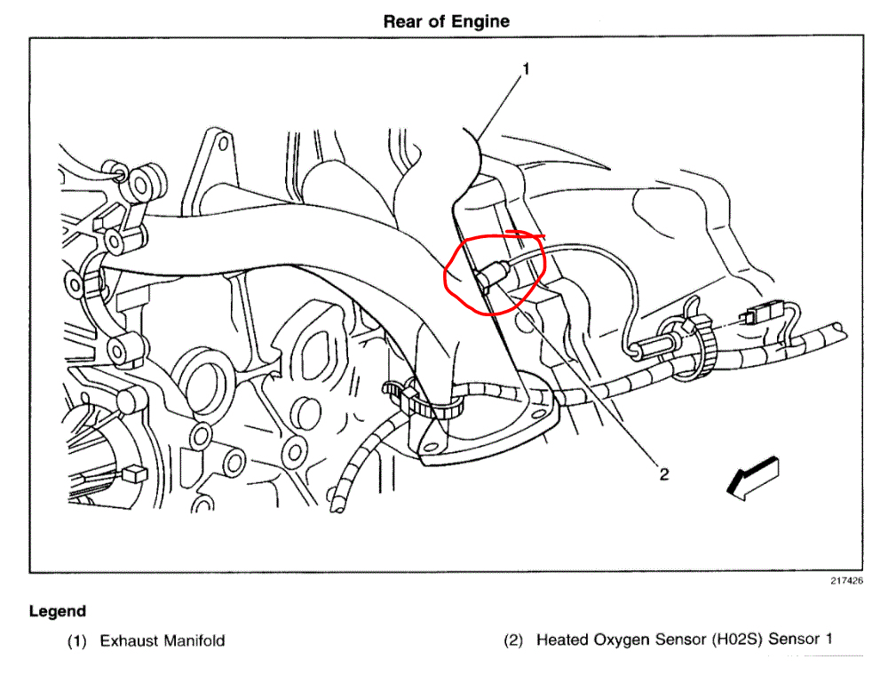
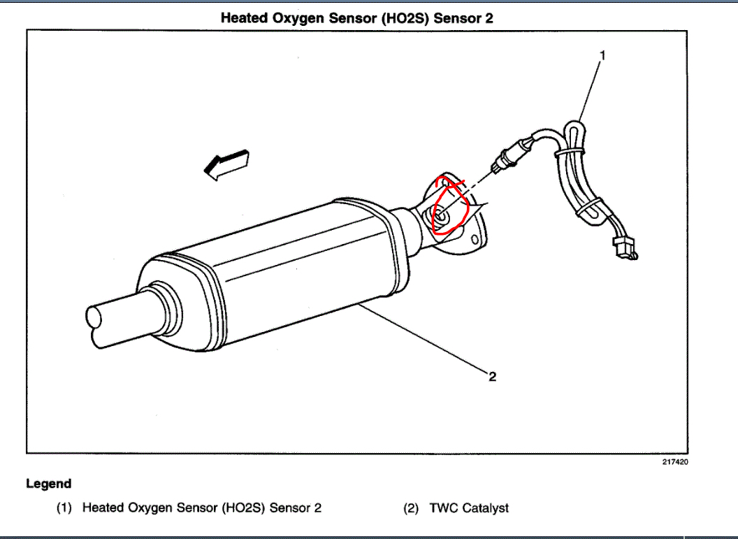
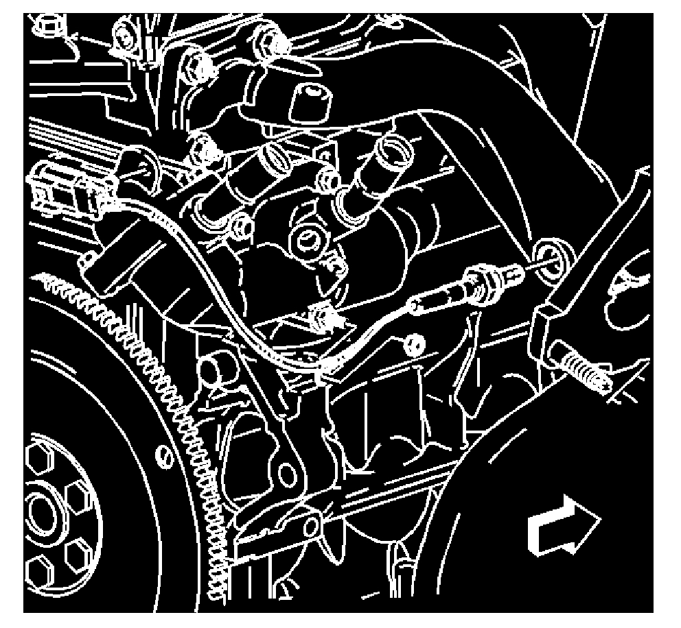
That sounds correct. There are two sensors on the vehicle, an upstream and downstream. The one you listed is for the upstream. It is mounted in the exhaust manifold. See pic 1. Sensor two (not listed above) is after the catalytic converter. See pic 2.
Here are the directions for replacing the one you listed. The attached pics correlate with the directions.
_______________________________
2004 Pontiac Sunfire L4-2.2L VIN F
Pre Catalytic Converter
Vehicle Powertrain Management Sensors and Switches - Powertrain Management Sensors and Switches - Computers and Control Systems Oxygen Sensor Service and Repair Procedures Pre Catalytic Converter
PRE CATALYTIC CONVERTER
REMOVAL PROCEDURE
NOTE:
- The oxygen sensor uses a permanently attached pigtail and connector. Do not remove the pigtail from the oxygen sensor. Damage to or removal of the pigtail connector could affect proper operation of the oxygen sensor.
- The use of excessive force may damage the threads in the exhaust manifold/pipe.
IMPORTANT:
- The in-line connector and louvered end must be kept clear of grease, dirt or other contaminants. Avoid using cleaning solvents of any type. DO NOT drop or roughly handle the oxygen sensor.
- The oxygen sensor may be difficult to remove when the engine temperature is less than 48°C (120°F).
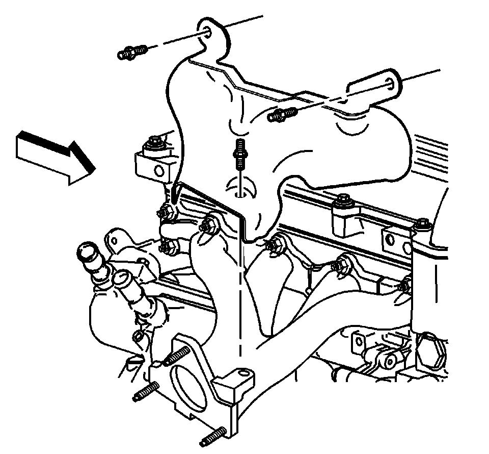
pic 3
1. Remove the exhaust manifold heat shield.
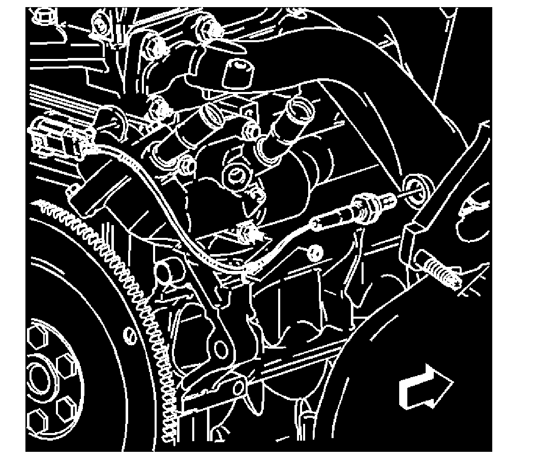
pic 4
2. Disconnect the oxygen sensor harness connector.
3. Remove the oxygen sensor.
INSTALLATION PROCEDURE
1. Coat the threads of the oxygen sensor with anti-seize compound, if necessary.
IMPORTANT: A special anti-seize compound is used on the oxygen sensor threads. The compound consists of a liquid graphite and glass beads. The graphite will burn away, but the glass beads will remain, making the sensor easier to remove. New or service sensors will have the compound applied to the threads. If a sensor is removed and is to be reinstalled, the threads must have an anti-seize compound applied before installation.
pic 5
2. Install the oxygen sensor.
NOTE: Refer to Fastener Notice in Service Precautions.
Tighten
Tighten the oxygen sensor to 30 N.m (22 lb ft).
3. Connect the oxygen sensor harness connector.
pic 6
4. Install the exhaust manifold heat shield.
_______________________________
Let me know if this helps or if you have other questions.
Take care and God Bless,
Joe
Images (Click to enlarge)
Mar 10, 2021 at 7:00 PM