Good morning,
With the valve removed from the manifold, start the car. You should have a large exhaust leak and a heavy vacuum leak. That will confirm the passages are clear for the valve to work.
I attached the flow chart for the code for you to view.
Roy
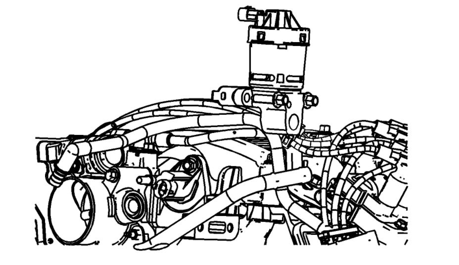
1. Disconnect the exhaust gas recirculation (EGR) valve electrical connector.
2. Remove the EGR pipe bolt and carefully pull the pipe assembly back.
3. Remove the EGR valve bolts.
4. Remove EGR valve.
5. Remove the EGR valve gasket.
6. Clean and inspect the EGR valve gasket mating surfaces.
DTC P0401
DTC DESCRIPTOR
DTC P0401
Exhaust Gas Recirculation (EGR) Flow Insufficient
DIAGNOSTIC FAULT INFORMATION
IMPORTANT: Always perform the Diagnostic System Check - Vehicle prior to using this diagnostic procedure. See: A L L Diagnostic Trouble Codes ( DTC ) > Testing and Inspection
CIRCUIT DESCRIPTION
The control module tests the exhaust gas recirculation (EGR) system during deceleration. The control module does this by momentarily commanding the EGR valve to open while monitoring the signal circuit of the manifold absolute pressure (MAP) sensor. When the EGR valve is opened, the control module will expect to see a predetermined increase in MAP. If the expected increase in MAP is not detected, the control module records the amount of MAP difference that was detected and adjusts a calibrated fail counter towards a calibrated fail threshold level. The number of EGR flow test counts required to exceed the fail threshold may vary according to the amount of detected EGR flow error.
The EGR valve position sensor is monitored by the control module. The 5-volt reference circuit, the low reference circuit, and the EGR valve position signal circuit are used by the control module to determine the EGR valve position. The control module compares the EGR Position Sensor parameter with the desired EGR Position parameter when the valve is commanded open or closed.
The control module controls the EGR valve with a solid state device called a driver. The driver supplies the EGR solenoid with 12 volts that is pulse width modulated (PWM) through the EGR solenoid high control circuit. A ground path is provided by the control module through the EGR solenoid low control circuit. The driver has the ability to detect an electrical malfunction on the EGR solenoid control circuits.
When the ignition switch is turned ON, the control module records the EGR Learned Minimum Position. The control module compares the EGR Learned Minimum Position parameter to the EGR Position Sensor parameter.
The control module will only allow one EGR flow test during an ignition cycle. To aid in verifying a repair, the control module will allow between 9-16 EGR flow test counts during the first ignition cycle following a code clear event.
CONDITIONS FOR RUNNING THE DTC
- DTCs P0068, P0101, P0102, P0103, P0107, P0108, P0112, P0113, P0117, P0118, P0120, P0201, P0202, P0203, P0204, P0205, P0206, P0220, P0300, P0335, P0403, P0404, P0405, P0502, P0503, P0506, P0507, P0604, P0606, P0641, P0651, P1106, P1107, P1125, P2101, P2108, P2135, U0107 are not set.
- The engine run time may need to be more than 3 minutes.
- The Ignition 1 Signal parameter is between 11-18 volts.
- The AC Relay Command parameter does not change.
- The EGR position is less than 1 percent.
- The transmission is in third or fourth gear.
- The Current Gear parameter does not change.
- The decel fuel cut-off (DFCO) mode is not active.
- The Intake Air Temperature (IAT) sensor parameter is between 5-100°C (41-212°F).
- The Engine Coolant Temperature (ECT) sensor parameter is between 75-123°C (167-253°F).
- The Engine Speed parameter is between 1,000-1,500 RPM.
- The Manifold Absolute Pressure (MAP) sensor parameter is between 17-43 kPa.
- The Barometric Pressure (BARO) parameter is more than 74 kPa.
- The Throttle Position (TP) sensor parameter is less than 1 percent.
- The Vehicle Speed sensor parameter is between 45-113 km/h (28-70 mph) during deceleration.
- The vehicle will need to be driven more than 80 km/h (50 mph), and then allowed to decelerate. When the vehicle is decelerating, while meeting all of the criteria listed above, the powertrain control module (PCM) will enable the EGR flow test to run. As the EGR flow test is running, you will see the desired EGR Position parameter and the EGR Position Sensor parameter on the scan tool momentarily change from 0 to a calibrated value above 0. Additionally, the EGR Flow Test Count parameter on the scan tool will increment when each EGR flow test is completed.
CONDITIONS FOR SETTING THE DTC
The MAP changes monitored by the PCM during the EGR flow tests indicate an insufficient amount of EGR flow.
ACTION TAKEN WHEN THE DTC SETS
- The control module illuminates the malfunction indicator lamp (MIL) on the second consecutive ignition cycle that the diagnostic runs and fails.
- The control module records the operating conditions at the time the diagnostic fails. The first time the diagnostic fails, the control module stores this information in the Failure Records. If the diagnostic reports a failure on the second consecutive ignition cycle, the control module records the operating conditions at the time of the failure. The control module writes the operating conditions to the Freeze Frame and updates the Failure Records.
CONDITIONS FOR CLEARING THE MIL/DTC
- The control module turns OFF the malfunction indicator lamp (MIL) after 3 consecutive ignition cycles that the diagnostic runs and does not fail.
- A current DTC, Last Test Failed, clears when the diagnostic runs and passes.
- A history DTC clears after 40 consecutive warm-up cycles, if no failures are reported by this or any other emission related diagnostic.
- Clear the MIL and the DTC with a scan tool.
DIAGNOSTIC AIDS
Inspect for the following conditions:
- A vacuum restriction to the MAP sensor-A skewed MAP sensor reading can cause the PCM to read incorrect MAP changes during the EGR flow test.
- An engine that is running poorly due to a mechanical condition, such as worn piston rings, worn camshaft, etc.-These types of conditions can cause low engine vacuum and thus can cause a less than expected MAP change during the flow test.
- Excessive back pressure in the exhaust system may cause this DTC to set. This condition can cause low engine vacuum and thus can cause a less than expected MAP change during the EGR flow test. Possible causes of this could be a restriction in the exhaust system or non original equipment manufacture (OEM) exhaust parts.
- Exhaust system leaks can cause an insufficient amount of EGR flow through the EGR valve. This condition can cause a less than expected MAP change due to insufficient exhaust back pressure. Possible causes of this could be a leaking exhaust system, a leaking EGR pipe or non-OEM exhaust parts.
- A restriction in the intake manifold such as carbon deposits and casting flash
CIRCUIT/SYSTEM VERIFICATION
Operate the vehicle within the Conditions for Running the DTC. Observe the EGR Flow Test Count parameter on the scan tool. EGR Flow Test counts may need to be as many as 16 to pass this DTC after the DTCs have been cleared.
CIRCUIT/SYSTEM TESTING
1. Test the MAP sensor for being shifted, stuck, skewed, and for correct vacuum supply. Refer to Manifold Absolute Pressure (MAP) Sensor Diagnosis. See: Computers and Control Systems > Component Tests and General Diagnostics > Manifold Absolute Pressure (MAP) Sensor Diagnosis
2. Inspect for a vacuum leak between the EGR valve and the intake manifold.
3. Inspect the exhaust system for leaks, restrictions, and for modification of OEM parts.
4. Remove the EGR valve and inspect for the following:
- Cracks
- Heat distress
- Pintle for corrosion
- EGR valve passages for restriction
- EGR passage in the intake manifold for carbon buildup, casting flash, or other restriction
- If a restriction is identified, refer to Exhaust Gas Recirculation (EGR) System Cleaning.
- If a condition with the EGR valve is identified, replace the EGR valve.
5. Inspect the engine for correct valve timing and lift or for other conditions that might affect engine vacuum source. Refer to Symptoms - Engine. See: Engine > Symptom Related Diagnostic Procedures
REPAIR INSTRUCTIONS
IMPORTANT:
- Engine Control Module Programming and Setup for control module replacement and programming
- Exhaust Gas Recirculation (EGR) Valve Replacement
REPAIR VERIFICATION
1. Clear the DTCs with a scan tool.
2. Turn OFF the ignition for 30 seconds.
3. Start the engine.
4. Operate the vehicle within the Conditions for Running the DTC. You may also operate the vehicle within the conditions that you observed from the Freeze Frame/Failure Records.
5. Observe the EGR Flow Test Count parameter on the scan tool. EGR Flow Test counts may need to be as many as 16 to pass this DTC after the DTCs have been cleared.
Images (Click to enlarge)
Mar 22, 2021 at 6:50 AM