Hi,
I don't have a video, but do have step by step directions. Here they are. Note that I am assuming this is a 2wd vehicle. If it is a 4wd, let me know.
_________________________________________________________________
2001 Ford Truck Ranger 2WD L4-2.3L VIN D
Removal
Vehicle Engine, Cooling and Exhaust Engine Service and Repair Procedures Engine Removal
REMOVAL
Engine
pic 1
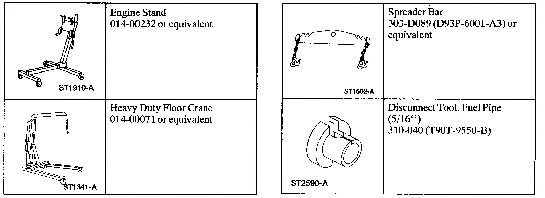
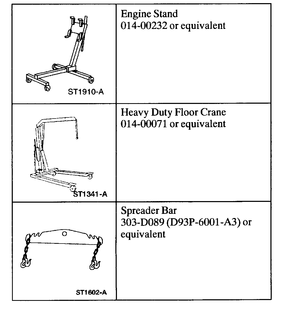
Special Tool(s)
1. Relieve the fuel pressure.
2. Disconnect the battery ground cable.
3. Recover the A/C system.
4. Drain the engine cooling system.
5. Drain the engine oil.
6. Remove the hood.
Pic 2
7. Remove the accelerator control snow shield.
8. Remove the air cleaner tube.
Pic 3
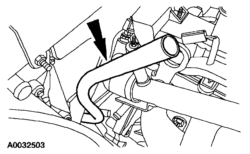
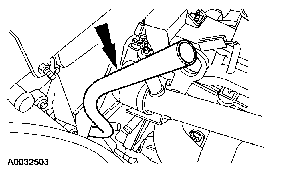
9. Remove the upper radiator hose.
Pic 4
10. Remove the lower radiator hose.
11. Remove the fan and shroud.
Pic 5
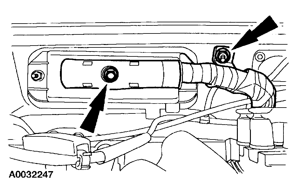
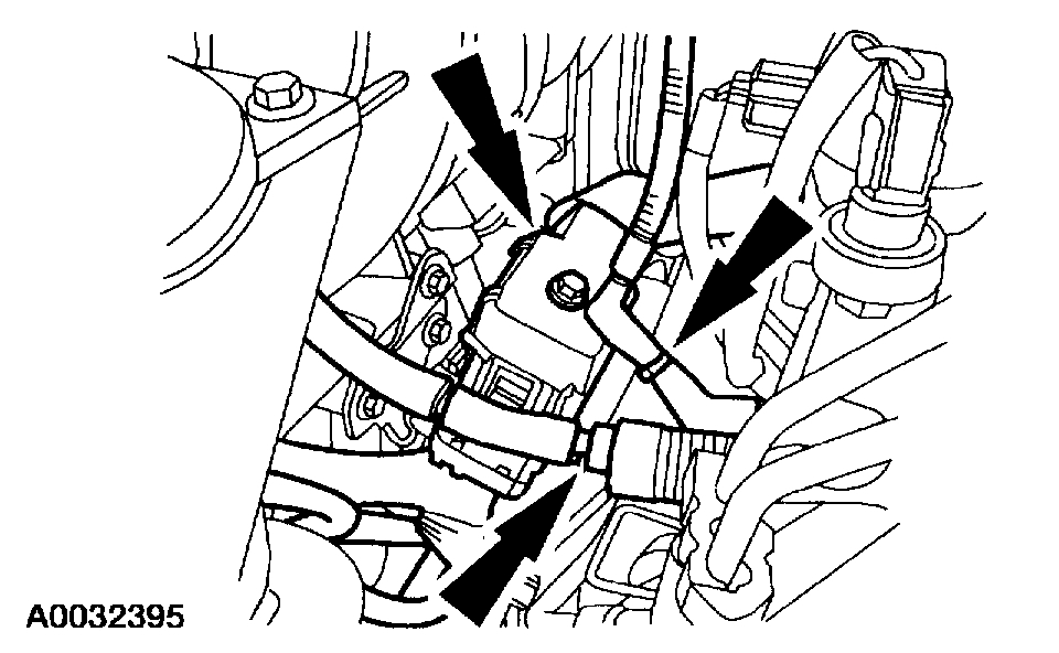
12. Disconnect the Powertrain Control Module (PCM) electrical connector. Remove the retaining nut on the harness clamp. Position the harness on the engine.
Pic 6
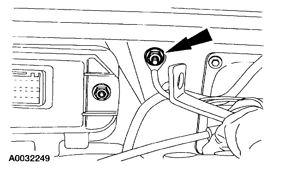
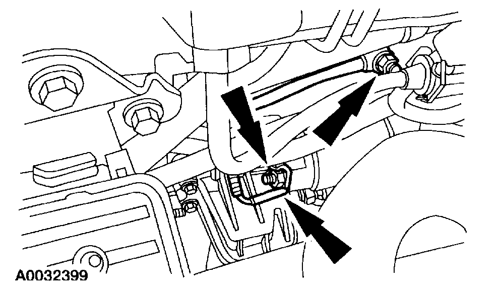
13. Remove the ground stud for the PCM.
Pic 7
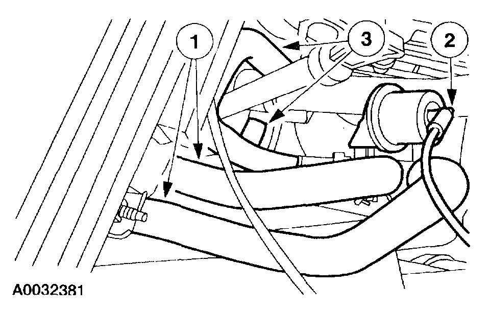
14. Remove the heater hose assembly.
1. Disconnect the heater water hoses at the bulkhead.
2. Disconnect the vacuum hose.
3. Disconnect the heater water hoses at the engine and remove the assembly.
Pic 8
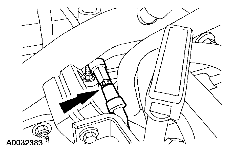
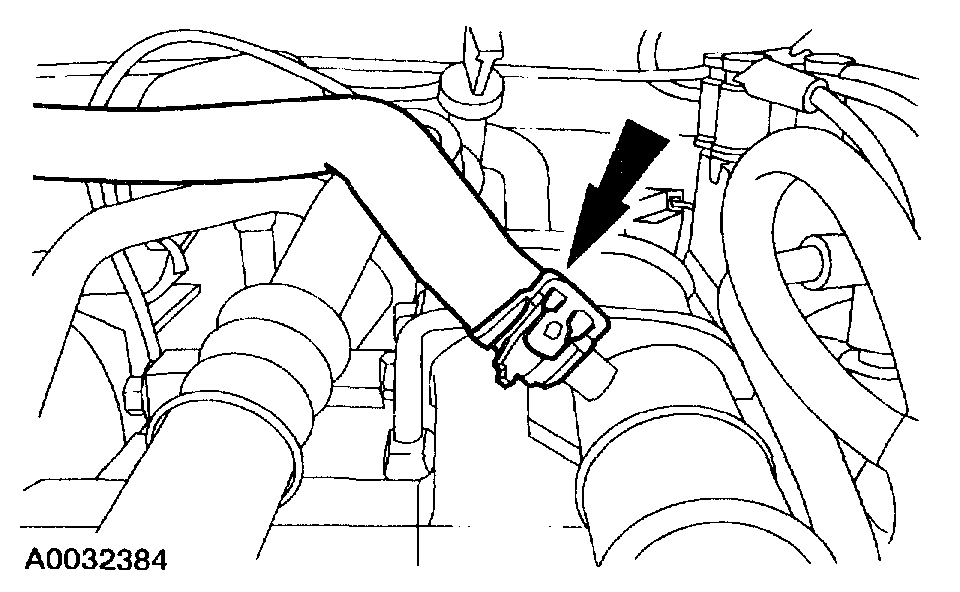
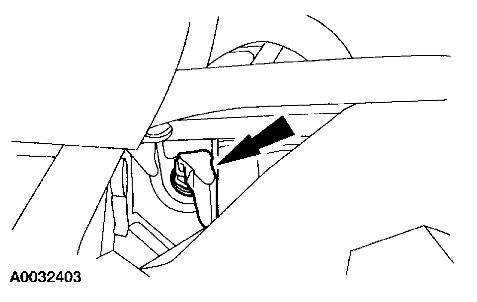
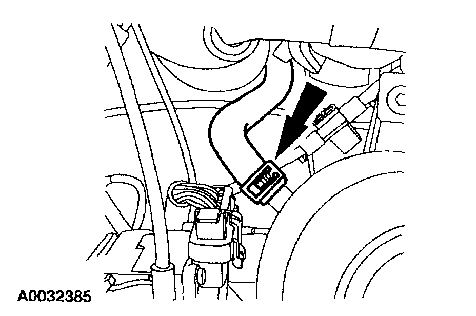
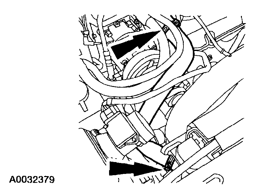
15. Disconnect the vacuum hose to the vacuum reservoir.
Pic 9
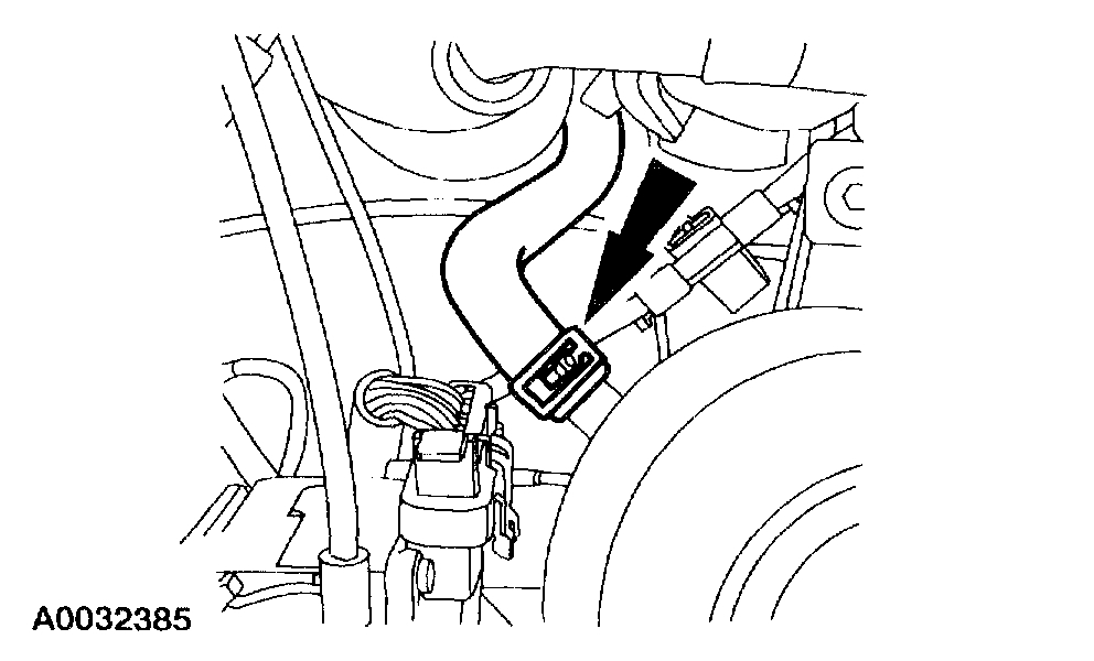
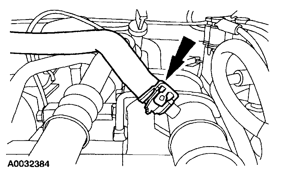
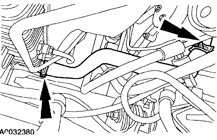
16. Disconnect the engine-to-coolant reservoir bypass hose.
Pic 10
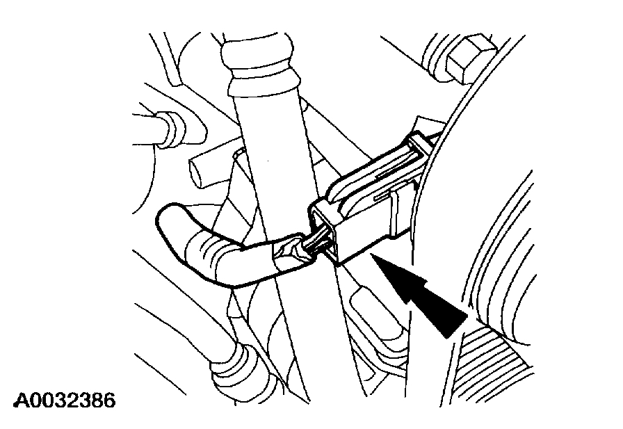
17. Disconnect the coolant reservoir-to-engine supply hose.
Pic 11
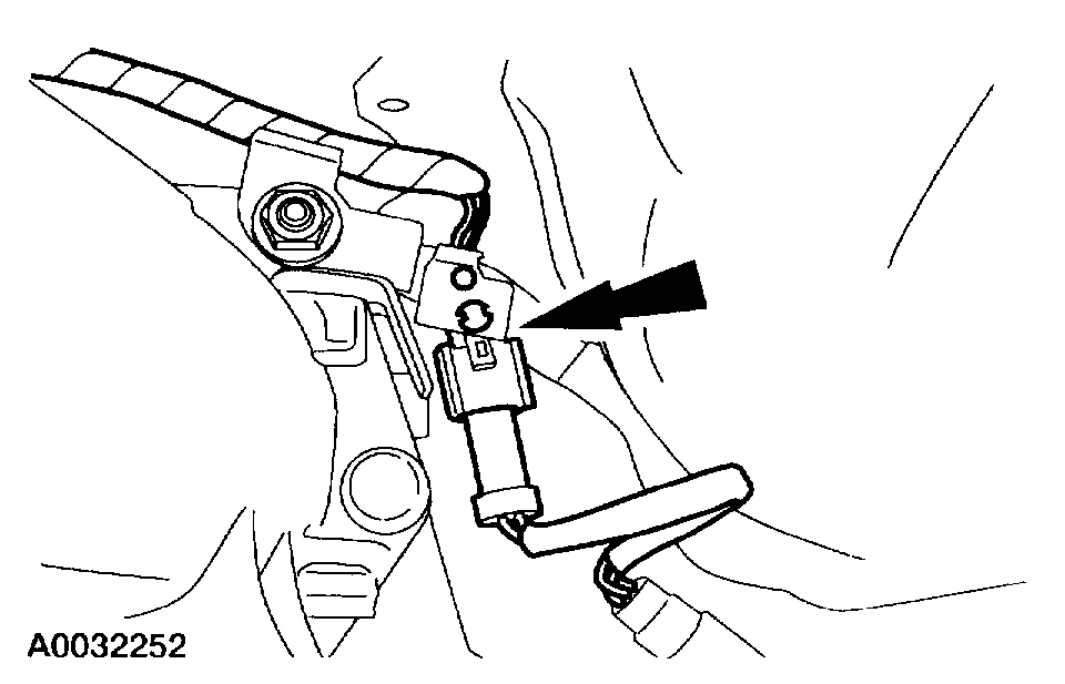
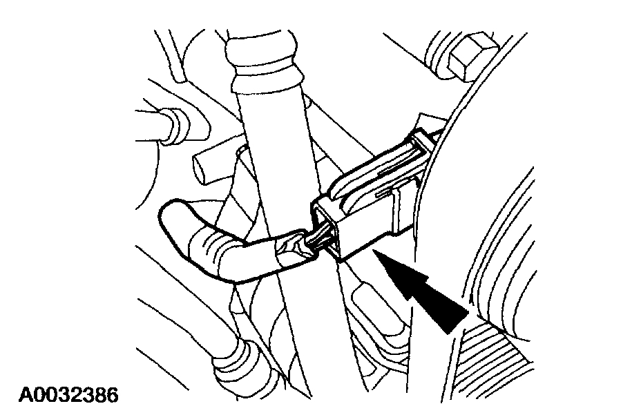
18. Disconnect the A/C compressor clutch.
Pic 12
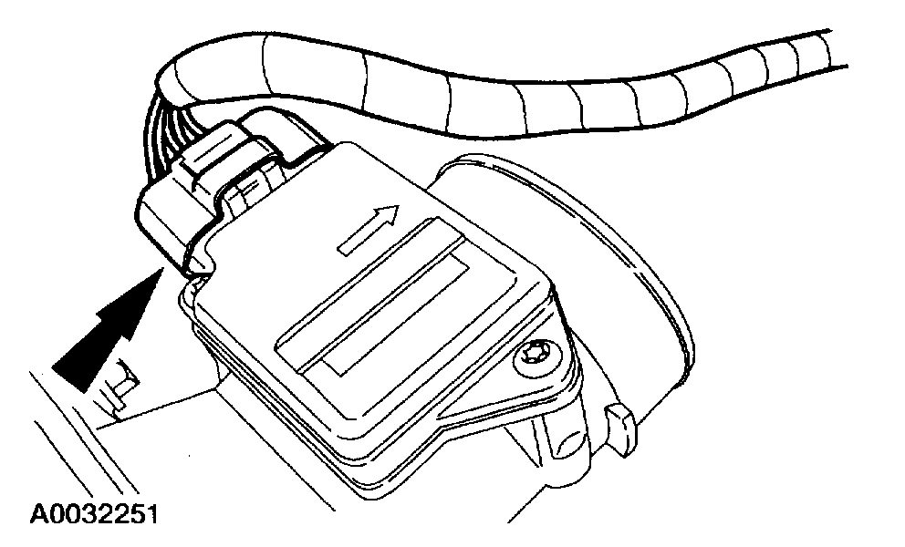
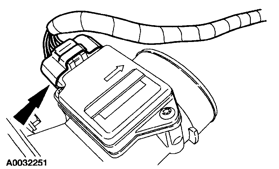
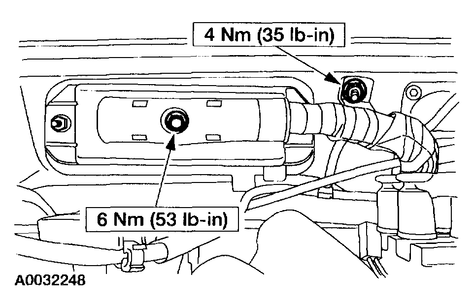
19. Disconnect the Mass Airflow Sensor (MAF) electrical connector.
Pic 13
20. Disconnect the A/C compressor manifold, plug the lines and the compressor ports.
Pic 14
21. Position the accelerator and speed control cables aside.
1. Disconnect the accelerator cable and speed control cable (if so equipped) from the throttle linkage.
2. Disconnect the accelerator cable and speed control cable (if so equipped) from the mounting bracket and position out of the way.
Pic 15
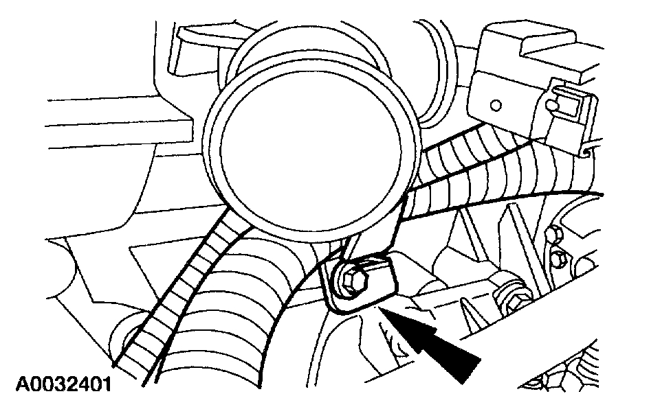
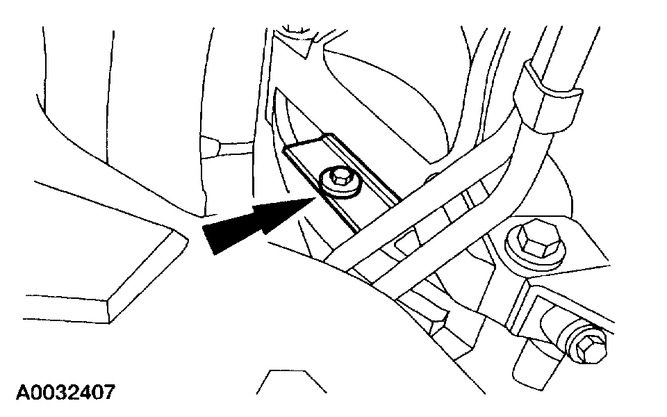
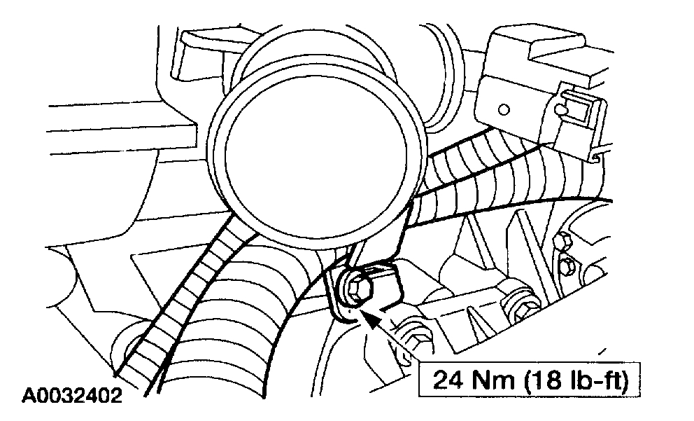
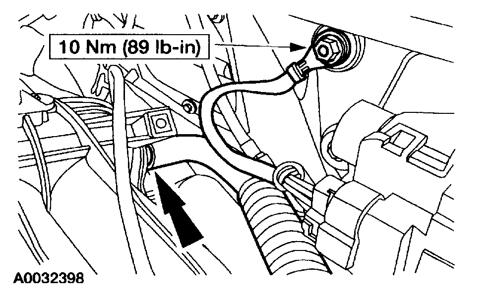
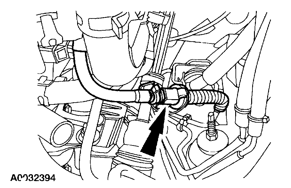
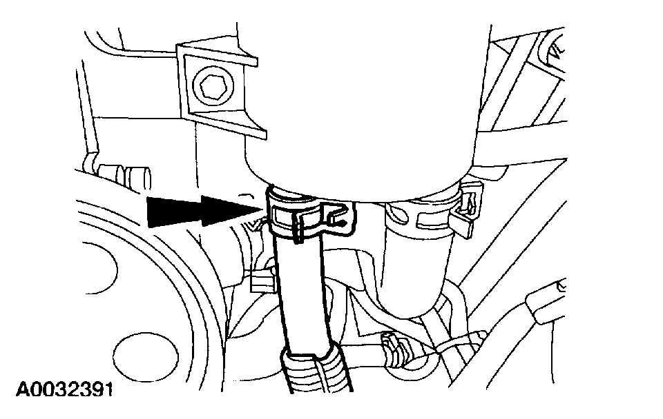
22. Disconnect the power steering return hose.
Pic 16
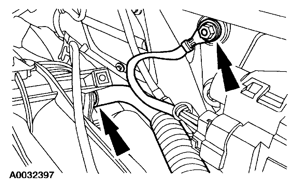
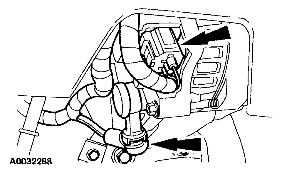
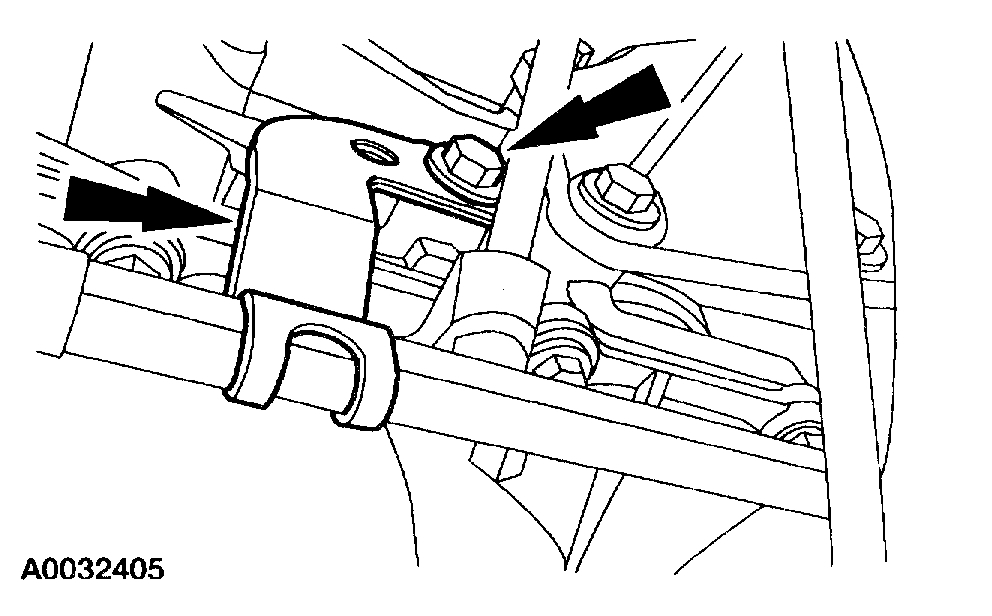
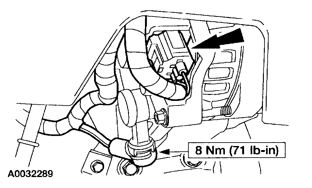
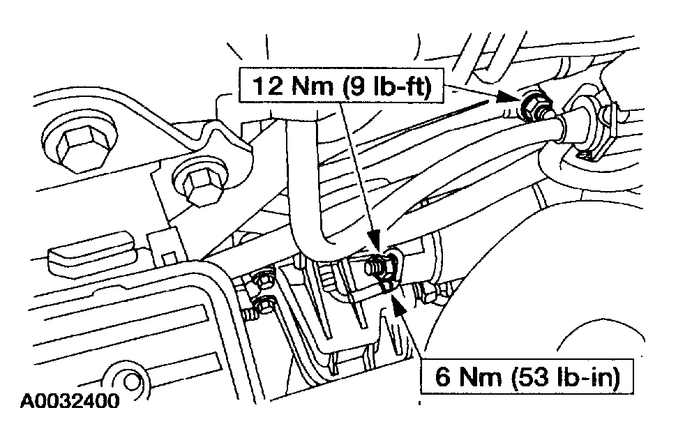
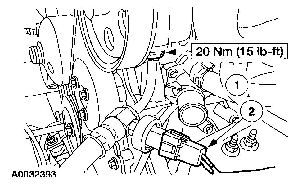
23. Disconnect the following:
The Power Steering Pressure (PSP) switch electrical connector.
The high pressure power steering hose.
Position the hose out of the way.
Pic 17
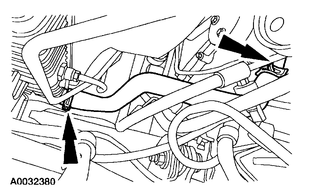
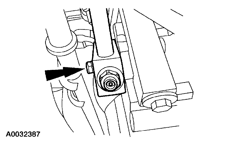
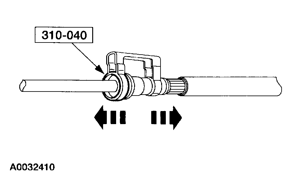
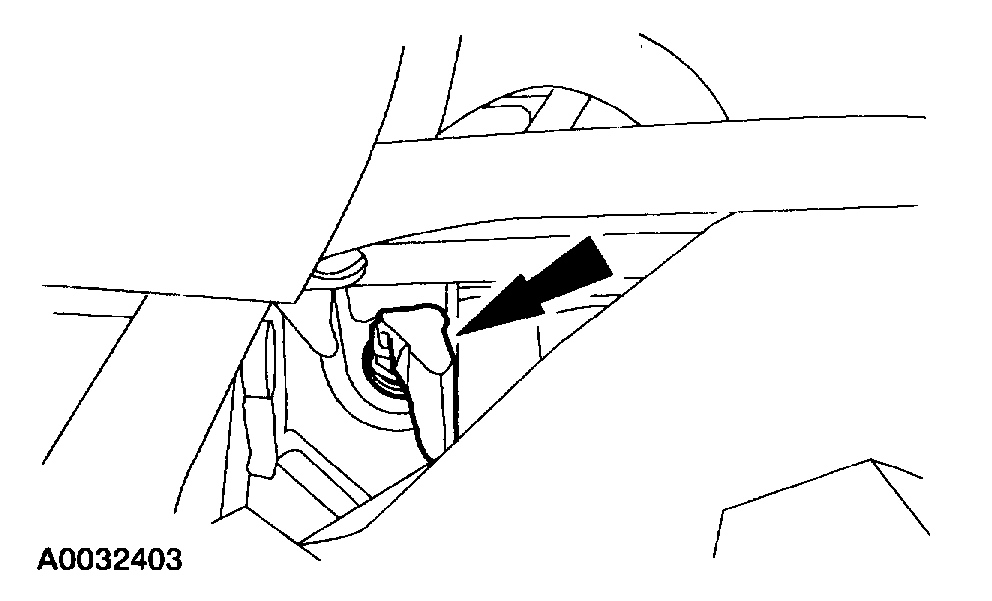
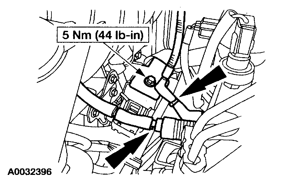
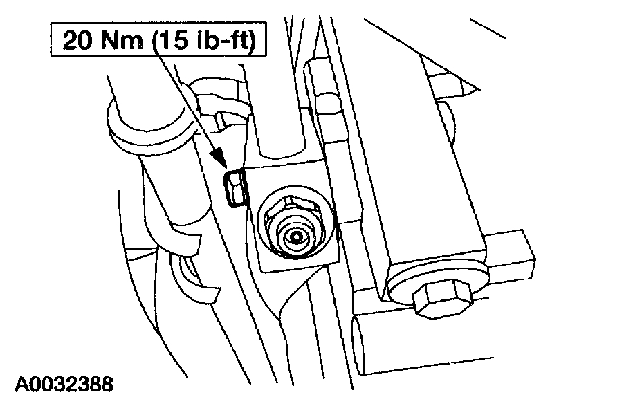
24. Remove the fuel line clip and using the special tool, disconnect the fuel supply hose.
Pic 18
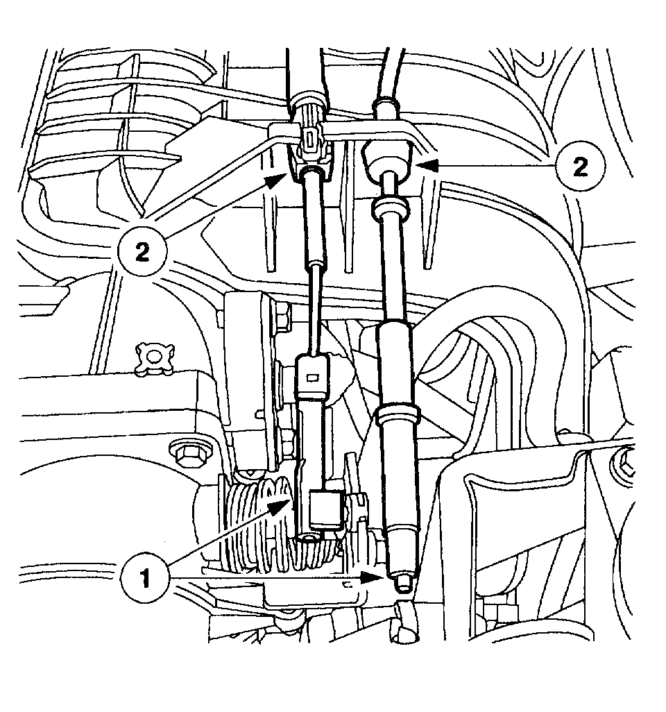
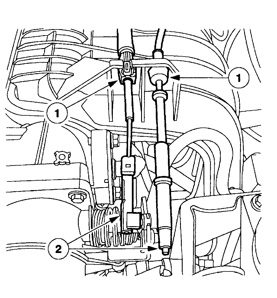
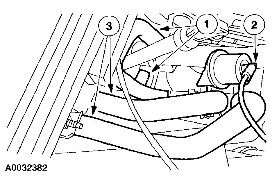
25. Disconnect the following:
42-pin electrical connector.
VMV vacuum regulator solenoid supply hose.
Evaporative purge hose.
Pic 19
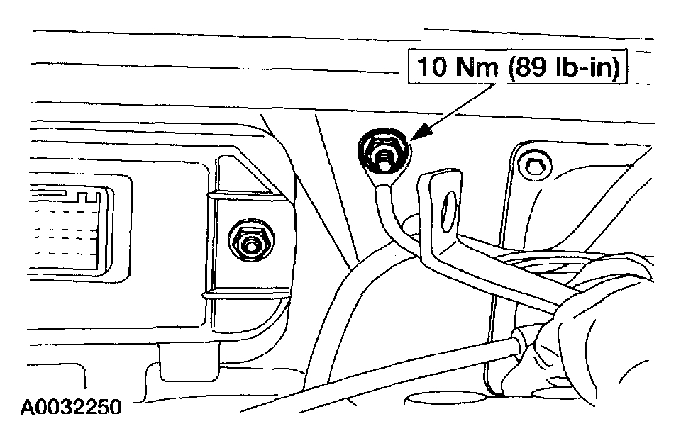
26. Disconnect the brake booster vacuum hose and the engine ground strap.
Pic 20
27. Disconnect the positive battery cable.
Disconnect the negative battery cable.
Disconnect the solenoid control wire at the starter.
Pic 21
28. Remove the starter wiring harness clamp bolt and position it out of the way.
29. Raise the vehicle on a hoist.
Pic 22
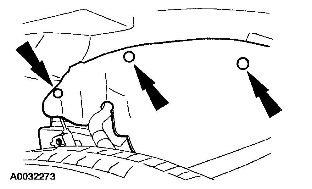
30. Position the RH splash shield out of the way.
Pic 23
31. Disconnect the alternator electrical connections.
Pic 24
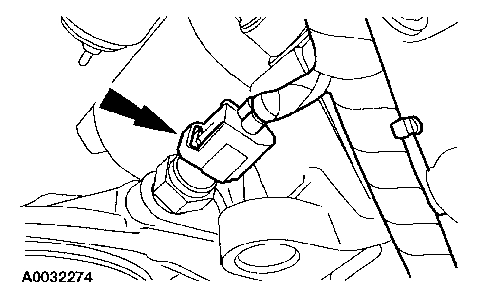
32. Disconnect the block heater electrical connector.
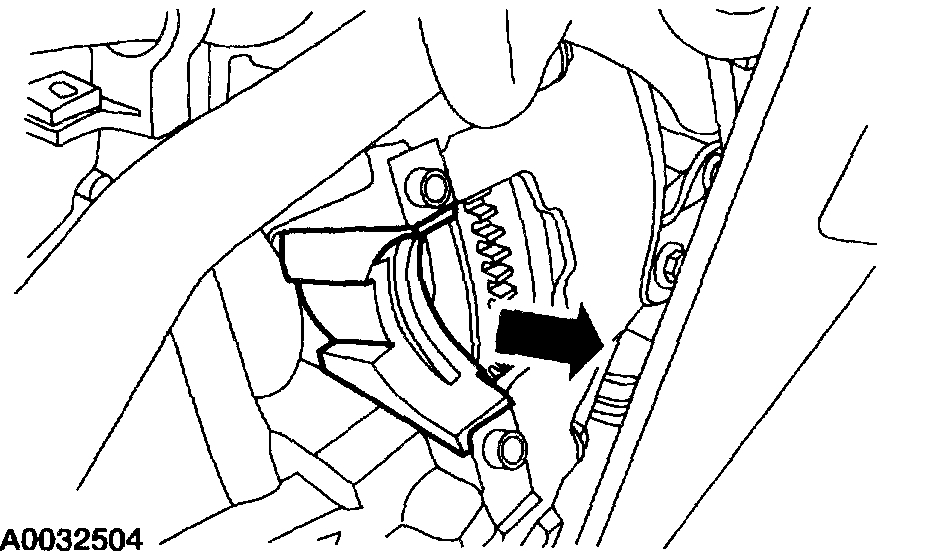
Pic 25
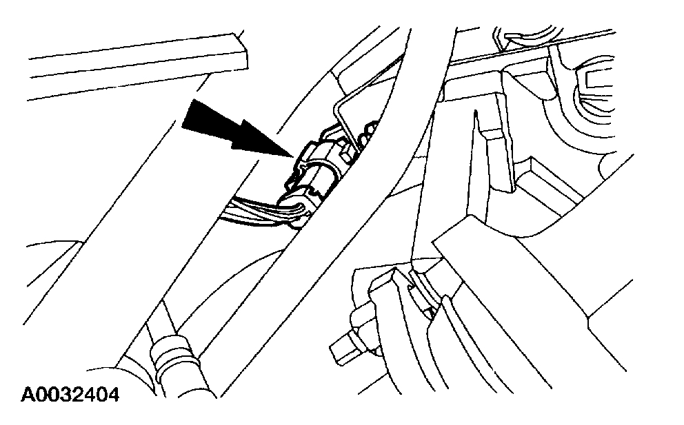
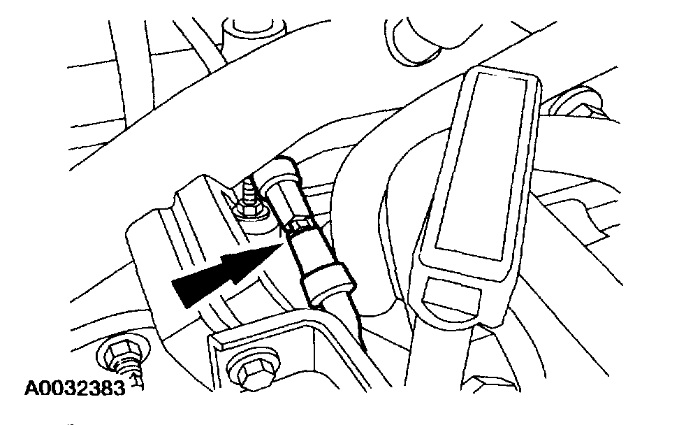
33. Disconnect the front Heated Oxygen Sensor (H02S) electrical connector at the bell housing.
Pic 26
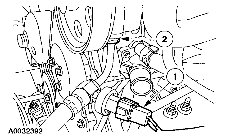
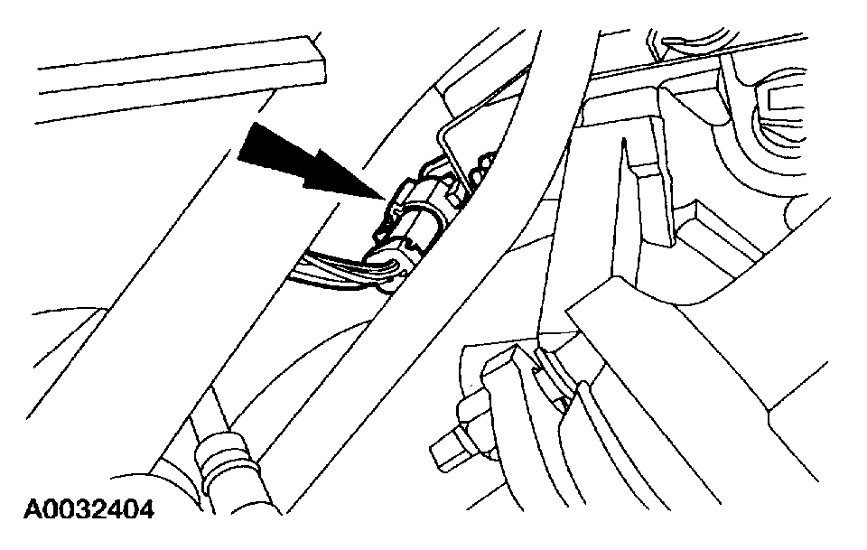
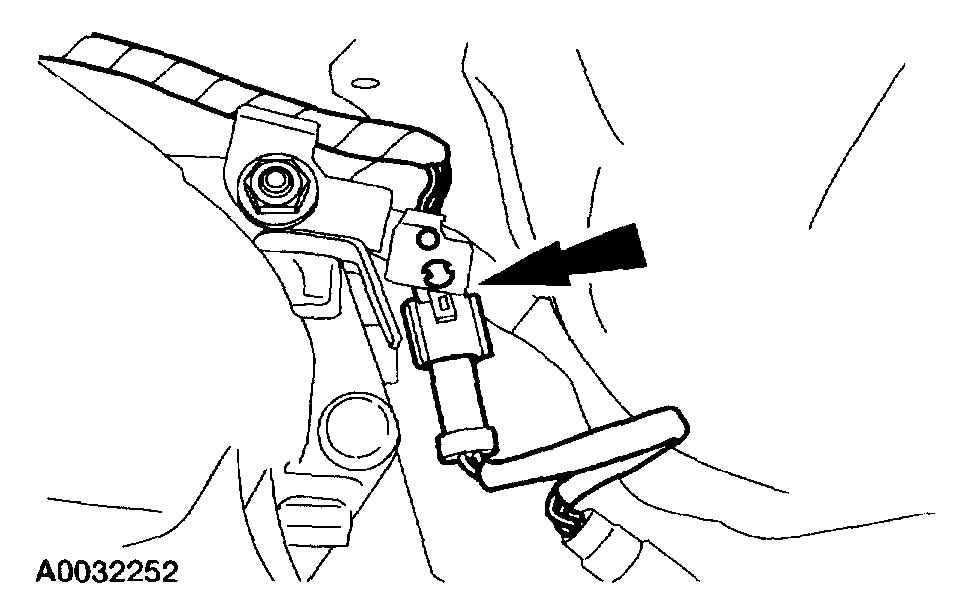
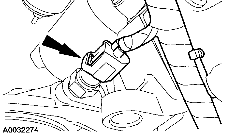
34. Disconnect the oil pressure sensor electrical connector
pic 27
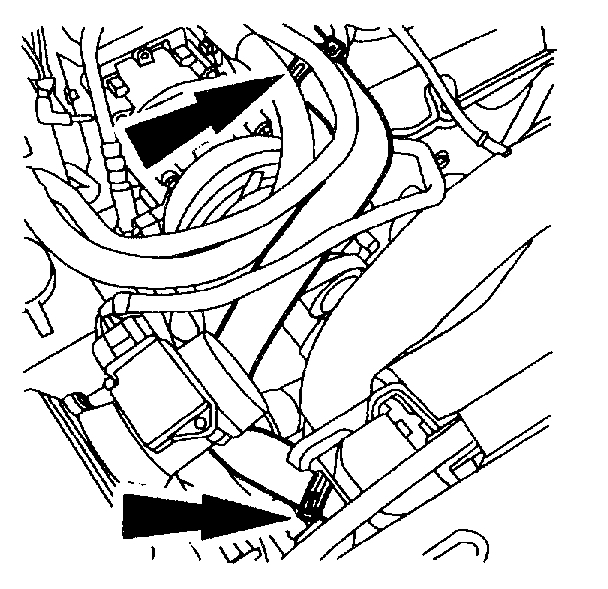
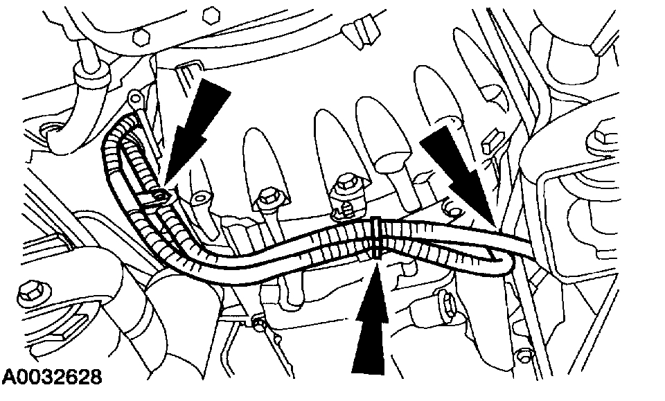
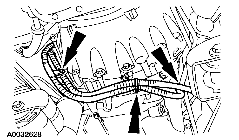
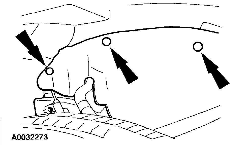
35. Disconnect the engine wiring pushpins and position the engine wiring harnesses out of the way.
Pic 28
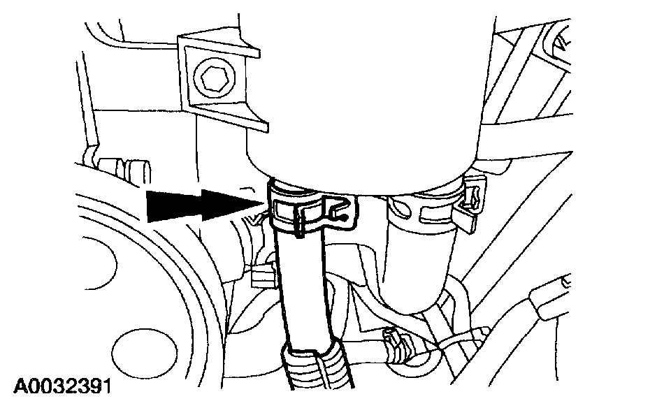
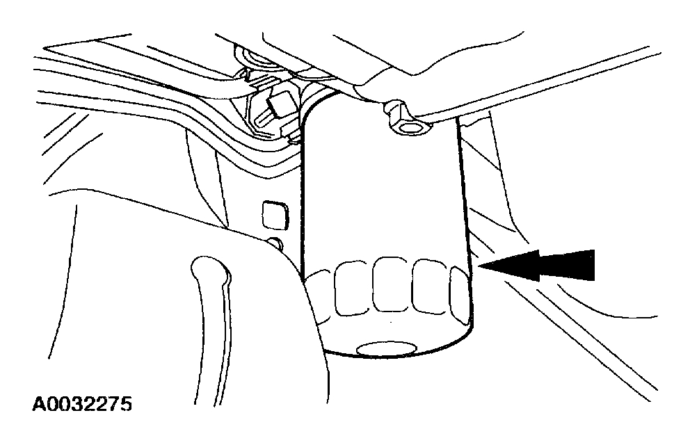
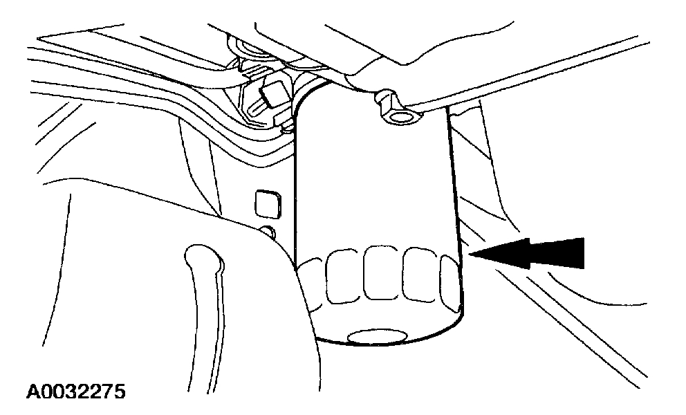
36. Remove the engine oil filter.
Pic 29
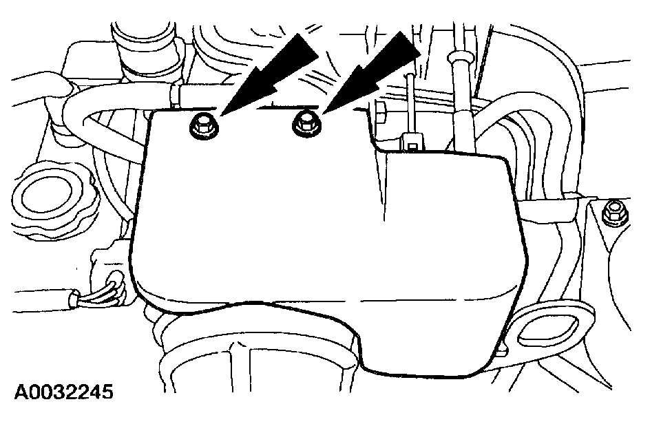
37. If the vehicle is equipped with an automatic transmission, remove the bolt retaining the transmission cooling tubes to the engine. Remove the bracket.
Pic 30
38. Remove the transmission dust shield.
Pic 31
39. Remove the nuts.
40. Remove the starter motor.
Pic 32
41. Disconnect the Heated Oxygen Sensor (HO2S) electrical connector at the rear of the transmission.
Pic 33
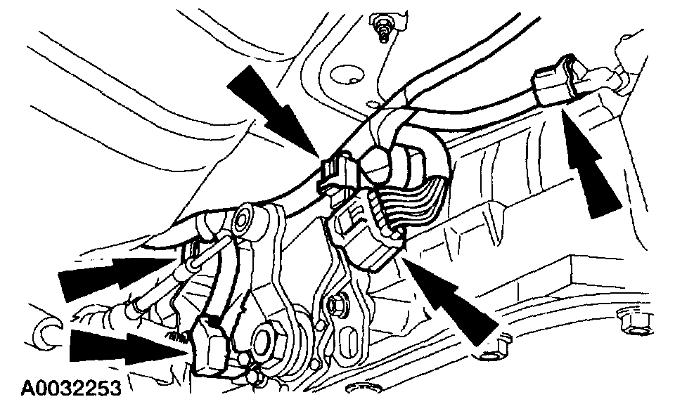
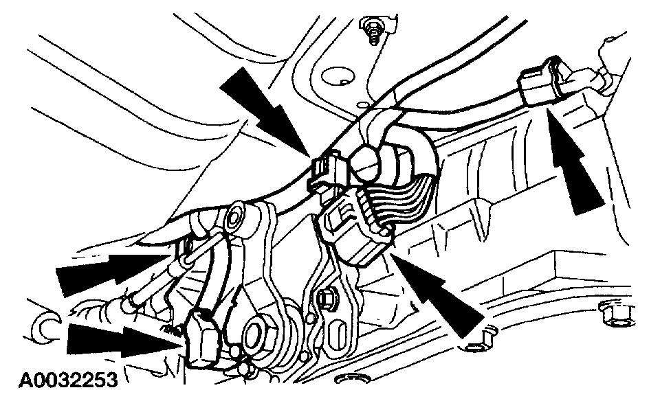
42. Disconnect the transmission wiring harness.
Disconnect the vehicle speed sensor, transmission range sensor, backup light switch and the transmission electrical connectors.
Disconnect the pushpins and position the harness forward to the engine.
Pic 34
43. Remove the oil filter adapter.
44. NOTE: Leave two side bolts in until the engine is ready to be removed.
Pic 35
Remove nine of the transmission-to-engine bolts.
45. Lower the vehicle.
Pic 36
46. On vehicles equipped with an automatic transmission, remove the transmission fluid indicator and tube assembly.
Pic 37
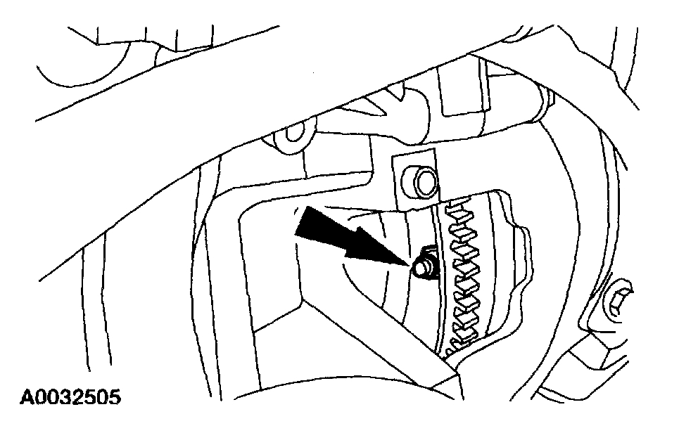
47. Remove the starter dust shield.
48. NOTE: Mark one stud and the flexplate for assembly reference.
Pic 38
On vehicles equipped with an automatic transmission, remove the four torque converter nuts.
49. Support the transmission with a floor jack.
50. Support the engine with the Floor Crane using the Spreader Bar.
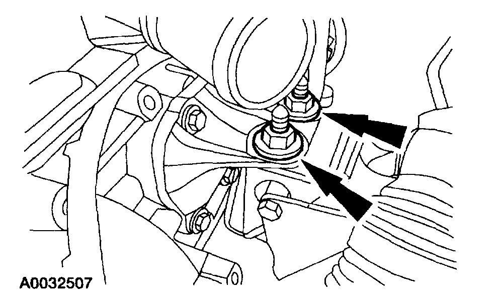
51. Remove the two side transmission-to-engine bolts.
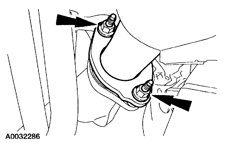
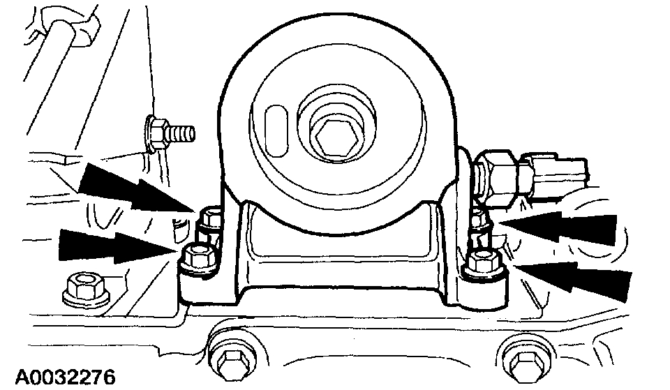
52. NOTE: Left side shown, right side similar.
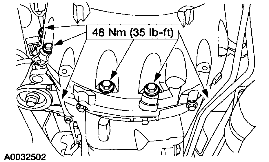
Pic 39
Remove the four engine support insulator.
53. Remove the engine from the vehicle.
54. On vehicles equipped with a manual transmissions. Remove the clutch.
Pic 40
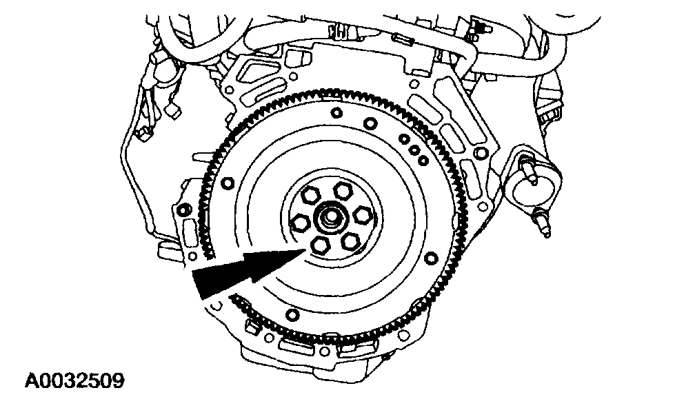
55. Remove the flywheel.
56. Mount the engine on a suitable work stand.
_____________________________________________________________________________________
Install
2001 Ford Truck Ranger 2WD L4-2.3L VIN D
Installation
Vehicle Engine, Cooling and Exhaust Engine Service and Repair Procedures Engine Installation
INSTALLATION
Engine
pic 41
Special Tool(s)
1. Using the Spreader Bar and the Floor Crane, remove the engine from the stand.
Pic 42
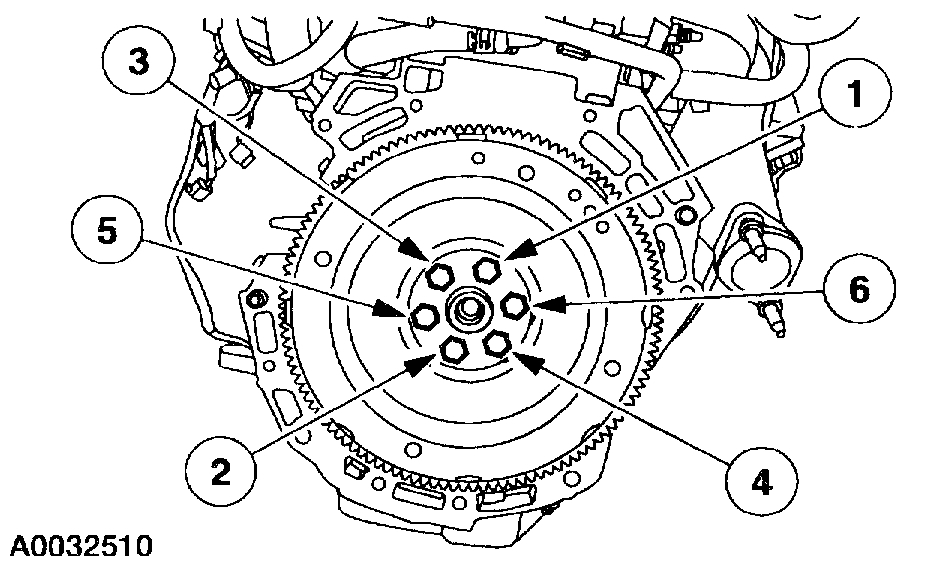
2. Install the flywheel and the bolts. Tighten the bolts in the sequence shown in three stages.
Stage 1: Tighten the bolts to 50 Nm (37 ft. Lbs.).
Stage 2: Tighten the bolts to 80 Nm (59 ft. Lbs.).
Stage 3: Tighten the bolts to 112 Nm (83 ft. Lbs.).
3. On vehicles equipped with a manual transmission, install the clutch.
4. Position the engine in the vehicle. On vehicles equipped with an automatic transmission, make sure the index marks on the torque converter stud and flexplate made during removal are lined up.
5. Install the two side transmission-to-engine bolts.
6. NOTE: Left side shown, right side similar.
Pic 43
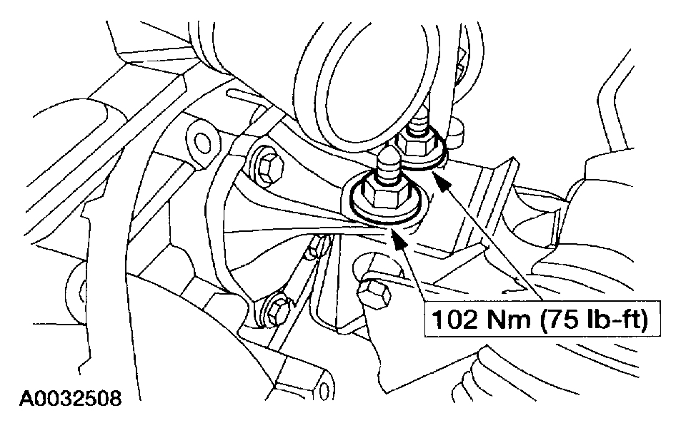
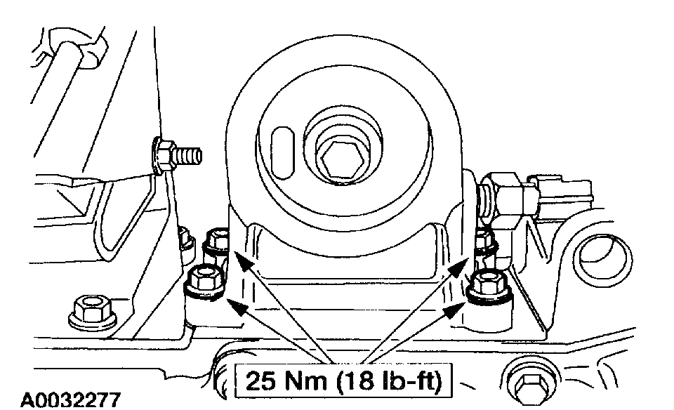
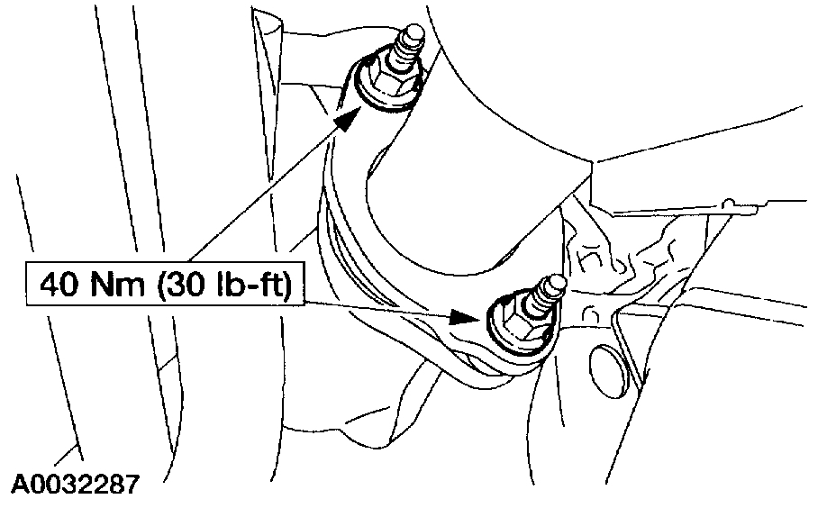
Install the four engine support insulator nuts.
7. Remove the floor jack from the transmission.
8. Remove the floor crane.
Pic 44
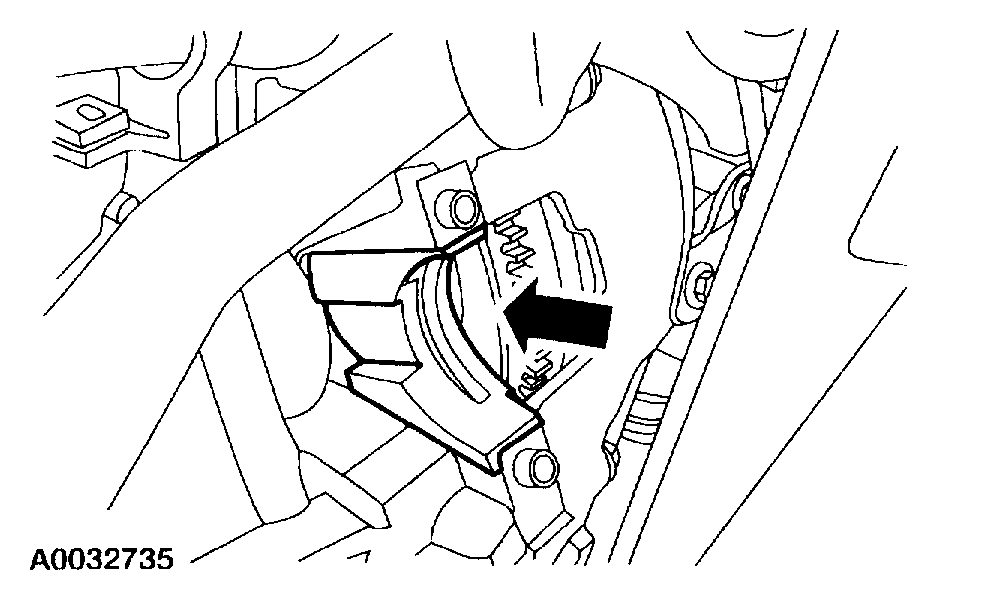
9. On vehicles equipped with an automatic transmission, install the four torque converter nuts.
Pic 45
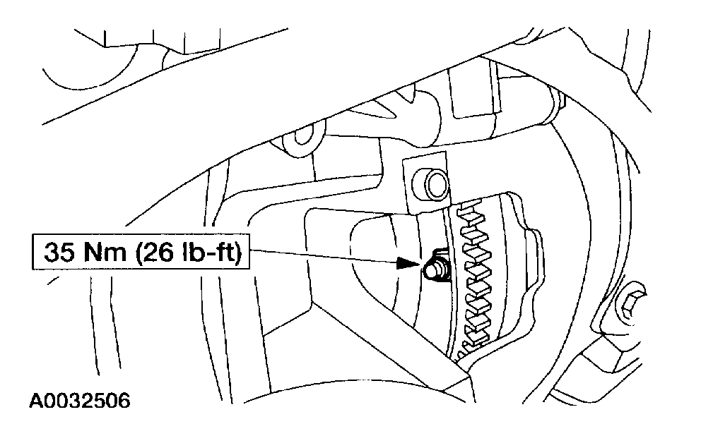
10. Install the starter dust shield.
Pic 46
11. On vehicles equipped with an automatic transmission, install the transmission fluid indicator and tube assembly.
12. Raise the vehicle.
Pic 47
13. Install the remaining nine transmission-to-engine bolts.
Pic 48
14. Install the oil filter adapter.
Pic 49
15. Connect the transmission wiring harness.
Position the transmission wiring and connect the pushpins.
Connect the transmission, the backup light switch, the transmission range sensor and the vehicle speed sensor electrical connectors.
Pic 50
16. Connect the H02S electrical connector at the rear of the transmission
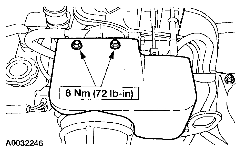
17. Install the starter.
Pic 51
18. Install the nuts.
Pic 52
19. Install the transmission dust shield.
Pic 53
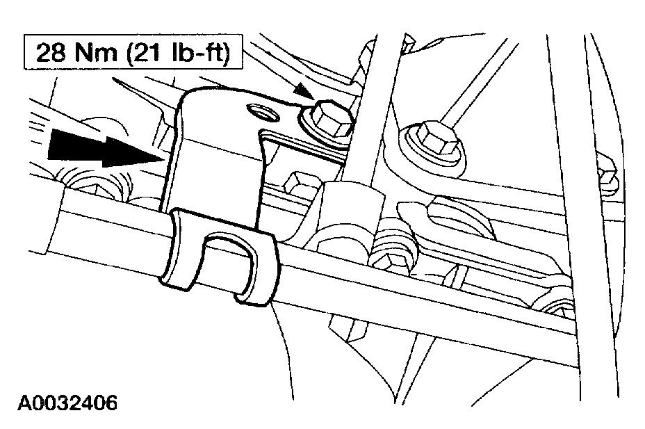
20. If the vehicle is equipped with an automatic transmission, install the bracket. Install the bolt retaining the transmission cooling tubes to the engine.
Pic 54
21. Install the oil filter.
Pic 55
22. Position the engine wiring harnesses and connect the pushpins.
Pic 56
23. Connect the oil pressure sensor electrical connector.
Pic 57
24. Connect the front H02S electrical connector at the bell housing.
Pic 58
25. Connect the block heater electrical connector.
Pic 59
26. Connect the alternator electric connectors.
Pic 60
27. Position the splash shield and install the pushpins.
28. Lower the vehicle.
Pic 61
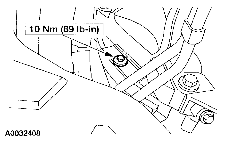
29. Position the starter wiring harness and install the bolt.
Pic 62
30. Connect the solenoid control wire, the negative battery cable and the positive battery cable at the starter.
Pic 63
31. Connect the brake booster vacuum hose and the engine ground strap.
Pic 64
32. Connect the following:
42-pin electrical connector.
VMV vacuum regulator solenoid supply hose.
Evaporative purge hose.
Pic 65
33. Connect the fuel supply hose and install the clip.
34. NOTE: Install a new nylon O-ring.
Pic 66
Connect the power steering high pressure hose and the power steering pressure switch electrical connector.
Pic 67
35. Connect the power steering return hose.
Pic 68
36. Connect the accelerator and speed control cables.
1. Position the accelerator cable and the speed control cable (if so equipped) into the mounting bracket.
2. Connect the accelerator cable and the speed control cable (if so equipped) to the throttle linkage.
Pic 69
37. Remove the plugs and connect the A/C compressor manifold.
Pic 70
38. Connect the MAF sensor electrical connector.
Pic 71
39. Connect the A/C compressor clutch electrical connector.
Pic 72
40. Connect the coolant reservoir-to-engine supply hose.
Pic 73
41. Connect the engine-to-coolant reservoir bypass hose.
Pic 74
42. Connect the vacuum hose to the vacuum reservoir.
Pic 75
43. Install the heater hose assembly.
1. Connect the heater water hoses to the engine.
2. Connect the vacuum hose.
3. Connect the heater water hoses to the heater core.
Pic 76
44. Install the ground stud for the PCM.
Pic 77
45. Position the PCM harness. Install the retaining nut on the harness clamp. Connect the PCM connector.
46. Install the fan and shroud.
Pic 78
47. Install the lower radiator hose.
Pic 79
48. Install the upper radiator hose.
49. Install the air cleaner tube.
Pic 80
50. Install the accelerator control snow shield.
51. Install the hood.
52. Fill the engine with clean engine oil.
53. Fill the engine cooling system.
54. Fill and bleed the power steering system.
55. Fill the A/C system.
56. Connect the battery ground cable.
__________________________________________________________________
I hope this helps. Let me know if you have questions.
Take care,
Joe
Images (Click to make bigger)
Thursday, March 5th, 2020 AT 6:19 PM