Good morning,
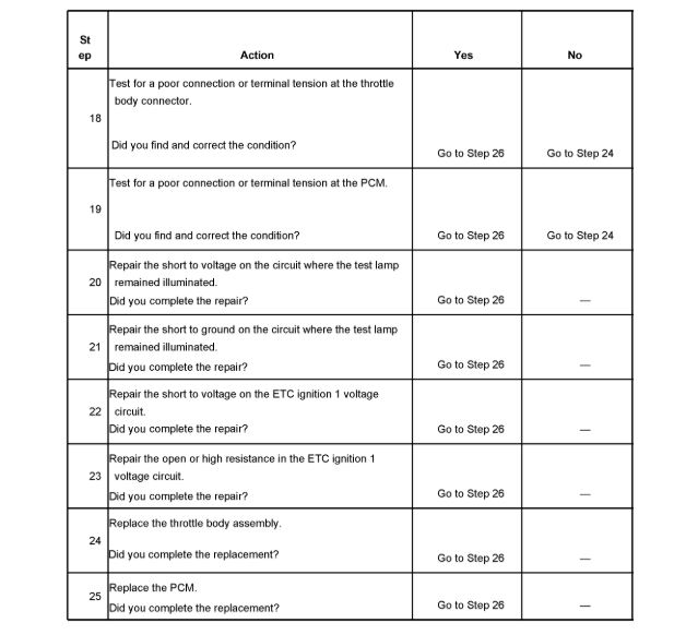
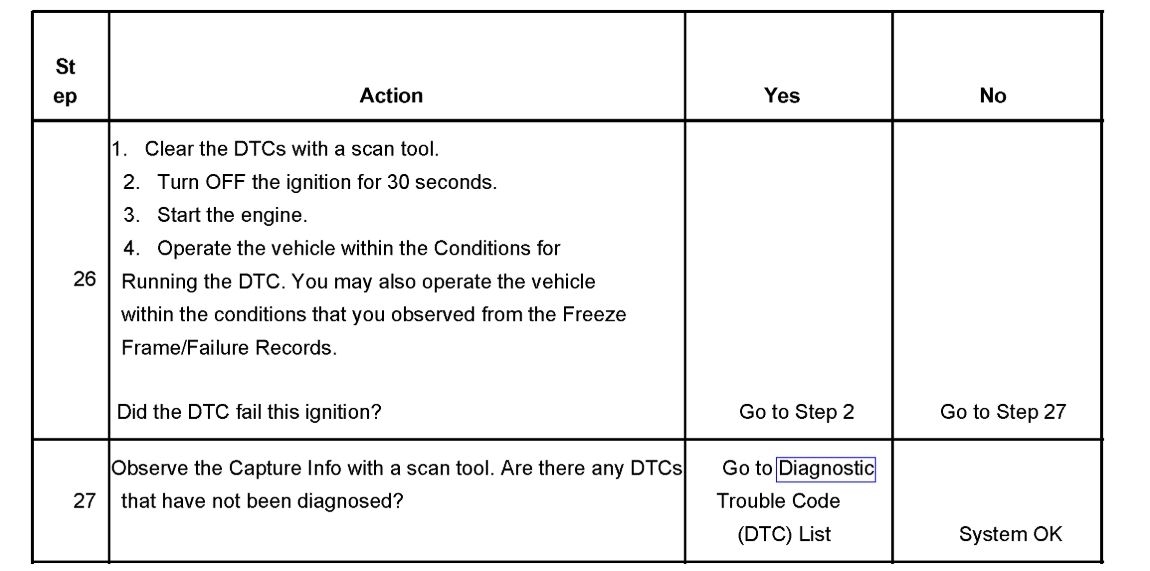
I attached a flow chart for you to follow for this.
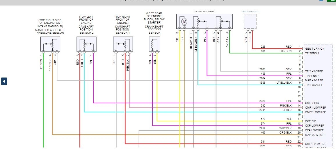
We need to do some wiring testing to see if the voltages are present at the sensor.
Do you have a voltmeter to do the testing?
https://www.2carpros.com/articles/door-panel-removal
Roy
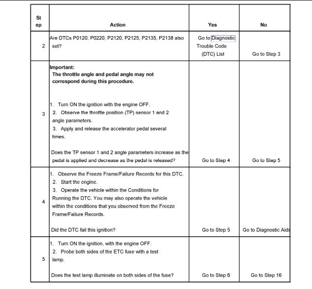
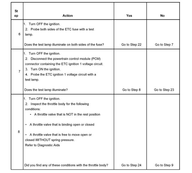
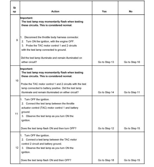
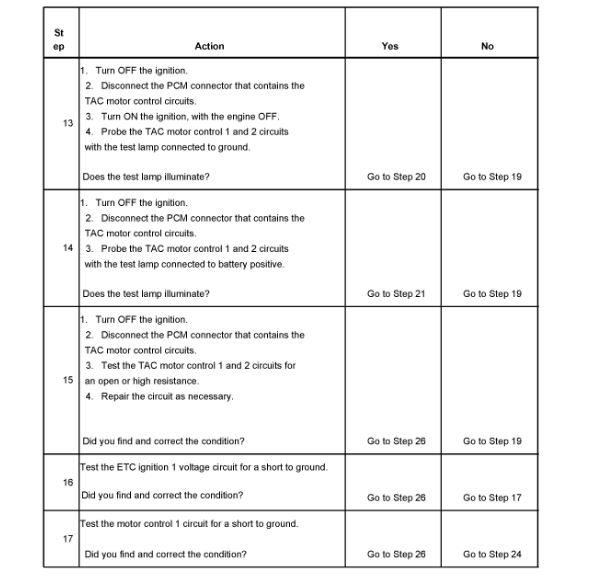
DTC P2101
CIRCUIT DESCRIPTION
The commanded throttle position (TP) is compared to the actual TP based on accelerator pedal position (APP) and possibly other limiting factors. Both values should be within a calibrated range of each other. The powertrain control module (PCM) continuously monitors the commanded and actual TPs. This DTC sets if the values are greater than the calibrated range.
CONDITIONS FOR RUNNING THE DTC
The ignition is ON.
The ignition voltage is greater than 8 volts.
The system is not in battery saver mode.
The engine is running.
DTC P0068 is not set.
CONDITIONS FOR SETTING THE DTC
The difference between the predicted throttle position and the actual throttle position is more than a calibrated amount.
ACTION TAKEN WHEN THE DTC SETS
The control module illuminates the malfunction indicator lamp (MIL) when the diagnostic runs and fails.
The control module records the operating conditions at the time the diagnostic fails. The control module stores this information in the Freeze Frame and/or the Failure Records.
The control module commands the TAC system to operate in the Reduced Engine Power mode.
A message center or an indicator displays Reduced Engine Power.
Under certain conditions the control module commands the engine OFF.
CONDITIONS FOR CLEARING THE MIL/DTC
The PCM turns OFF the MIL after 3 consecutive drive trips that the diagnostic runs and passes.
A History DTC clears after 40 consecutive warm-up cycles in which there are no failures reported of this diagnostic or any other emission related diagnostic.
The scan tool clears the MIL/DTC.
DIAGNOSTIC AIDS
The throttle valve is spring loaded to a slightly open position. The throttle valve should be open approximately 20 percent. This is referred to as the rest position. The throttle valve should not be completely closed nor should they be open any more than the specified amount. The throttle valve should move open and to the closed position without binding under the normal spring pressure. The throttle should NOT be free to move open or closed WITHOUT spring pressure. Replace the throttle body if any of these conditions are found.
IMPORTANT: Operating the throttle blade with the Throttle Blade Control function of the scan tool may cause additional DTCs to set. DO NOT attempt to diagnose DTCs set during this function.
The scan tool has the ability to operate the throttle control system using Special Functions. Actuate the throttle valve using the throttle blade control function located in the throttle actuator control (TAC) System menu. This function will operate the throttle valve through the entire range in order to determine if the throttle body and system operate correctly.
Inspect for the following conditions:
Use the J 35616-B Connector Test Adapter Kit for any test that requires probing the PCM harness connector or a component harness connector.
Poor connections at the PCM or at the component. Inspect the harness connectors for a poor terminal to wire connection.
For intermittents, refer to Intermittent Conditions. See: Computers and Control Systems > Initial Inspection and Diagnostic Overview > Intermittent Conditions
Images (Click to make bigger)
Tuesday, June 30th, 2020 AT 5:31 AM