Hi,
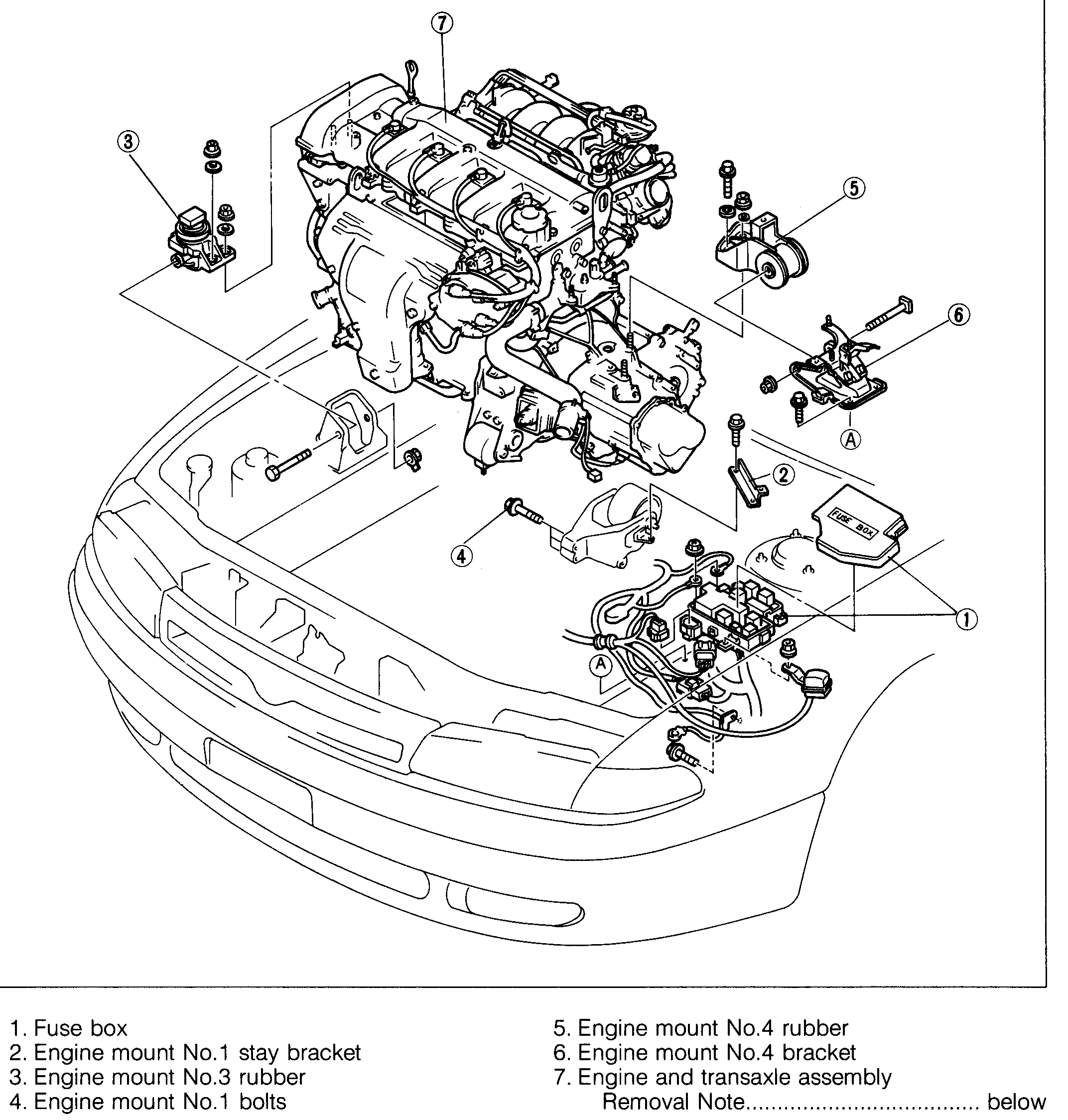
If you are referring to the one in the rear of the engine, the engine mount cross member needs removed to access it. This requires the engine to be supported via a chain/engine hoist.
Here are the directions I have for replacement. The attached pictures correlate with the directions. I have to be honest, it is somewhat vague, but does describe the correct process.
________________________________________
1998 Mazda 626 DX L4-2.0L DOHC
Removal
Vehicle Engine, Cooling and Exhaust Engine Drive Belts, Mounts, Brackets and Accessories Engine Mount Service and Repair Procedures Removal
REMOVAL
pic 1
pic 2
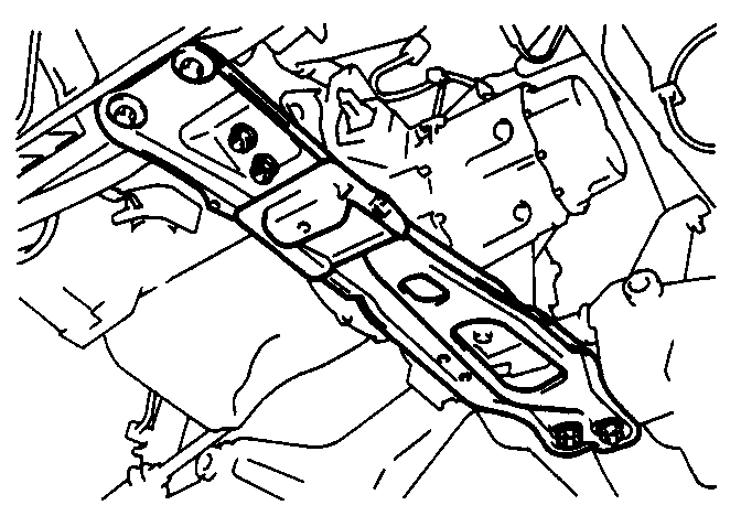
Engine mount member
Caution
- Support the engine before removing the member.
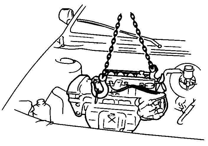
pic 3
1. Suspend the engine by using a chain block.
2. Remove the engine mount No.2 nuts.
3. Remove the engine mount member bolts and nuts and remove the engine mount member.
________________________
1998 Mazda 626 DX L4-2.0L DOHC
Installation
Vehicle Engine, Cooling and Exhaust Engine Drive Belts, Mounts, Brackets and Accessories Engine Mount Service and Repair Procedures Installation
INSTALLATION
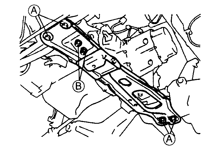
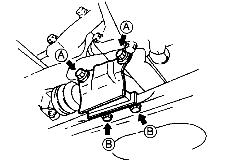
pic 4
Engine Mount Installation
1. Hand tighten the nuts marked (B). (No 2 engine mount)
2. Install the bolts and nuts shown.
Tightening torque
(A): 67-93 N.m (6.8-9.5 kgf.m, 50-68 ft.lbf)
pic 5
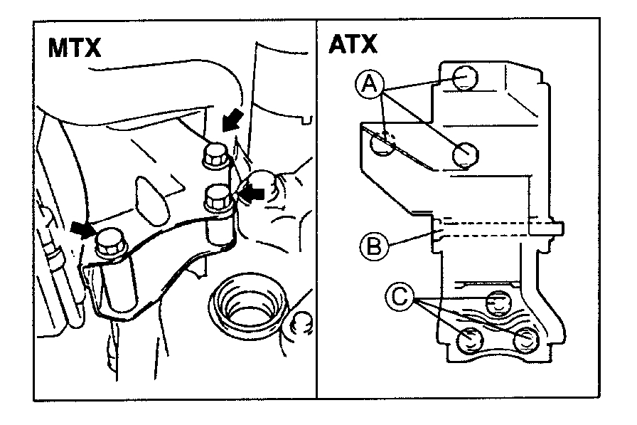
3. Install the No.1 engine mount mounting bolts.
Tightening torque
MTX: 67-93 Nm (6.8-9.5 kgf.m, 50-68 ft.lbf)
ATX
(A): 67-104 N.m (6.8-10.7 kgf.m, 50-77.3 ft.lbf)
(B): 86-116 N.m (8.7-11.9 kgf.m, 63-86.0 ft.lbf)
(C): 67-93 N.m (6.8-9.5 kgf.m, 50-68 ft.lbf)
pic 6
4. Install the No.3 engine mount rubber.
Tightening torque
Nut: 74-102 N.m (7.5-10.5 kgf.m, 55-75.9 ft.lbf)
Bolt: 86-116 N.m (8.7-11.9 kgf.m, 6-6.0 ft.lbf)
pic 7
5. Install the No.4 engine mount bracket.
6. Hand tighten bolts (B).
7. Tighten bolts (B).
8. Tighten bolts (A).
Tightening torque
(A): 59-80 N.m (6.0-8.2 kgf.m, 44-59 ft.lbf)
(B): 59-80 N.m (6.0-8.2 kgf.m, 44-59 ft.lbf)
pic 8
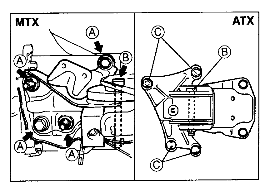
9. Install the No.4 engine mount rubber.
Tightening torque
MTX
(A): 67-93 N.m (6.8-9.5 kgf.m, 50-68 ft.lbf)
(B): 86-116 Nm (8.7-11.9 kgf.m, 63-86.0 ft.lbf)
ATX
(C): 38-51 N.m (3.8-5.3 kgf.m, 28-38 ft.lbf)
10. Remove the chain from the engine hangers.
11. Tighten the No.2 engine mount nuts. (Refer to step 1.)
Tightening torque:
75-104 Nm (7.6-10.7 kgf.m, 55-77.3 ft.lbf)
pic 9
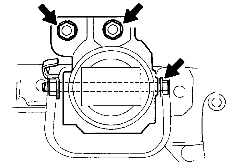
12. Tighten the No.2 engine mount rubber through bolt.
Tightening torque:
86-116 Nm (8.7-11.9 kgf.m, 63-86.0 ft.lbf)
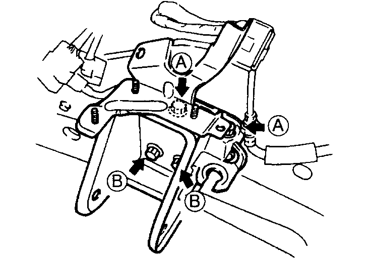
13. Install the No.5 engine mount rubber as shown.
Tightening torque
(A): 55-80 Nm (5.6-8.2 kgf.m, 41-59 ft.lbf)
(B): 44-60 Nm (4.4-6.2 kgf.m, 32-44 ft.lbf)
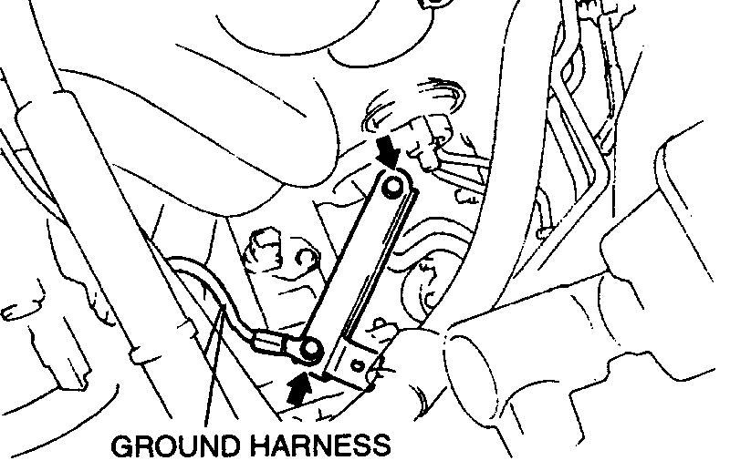
pic 10
14. Install the No.1 engine mount stay bracket and ground harness (MTX).
Tightening torque:
6.9-9.8 N.m (70-100 kgf.cm, 61-86.8 in.lbf)
____________________________________
Let me know if this helps or if you have other questions.
Take care,
Joe
Images (Click to enlarge)
Apr 24, 2020 at 9:29 PM