Good evening,
Attached is the procedure for you.
Roy
Differential Overhaul (11.5 Inch Axle)
Tools Required
J 8092 Universal Driver Handle - 3/4 in - 10
J 22888-D Side Bearing Remover Kit
J 44420 Differential Bearing and Hub Seal Installer
Disassembly Procedure
imageOpen In New TabZoom/Print
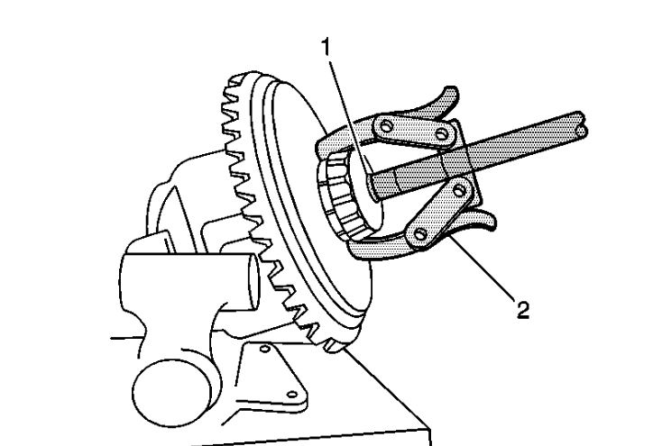
1. Remove the differential side bearings by performing the following steps:
1. Install the differential assembly into a vise.
2. Install the J 8107-5 (1) and the J 22888-20A (2) as shown.
3. Remove the differential side bearings using the J 22888-20A.
imageOpen In New TabZoom/Print
2. Remove the gear bolts. Discard the bolts.
Important: The ring gear bolts have right-hand threads.
imageOpen In New TabZoom/Print
3. Remove the ring gear from the differential case. Drive the ring gear off with a brass drift if necessary.
Notice: Refer to Ring Gear Removal Notice in Service Precautions.
imageOpen In New TabZoom/Print
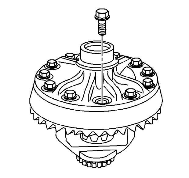
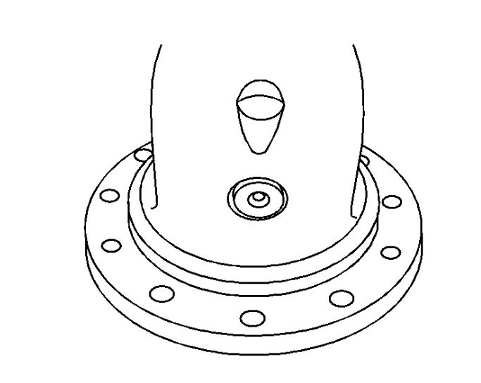
4. Locate the end of the pinion shaft with the pilot hole.
imageOpen In New TabZoom/Print
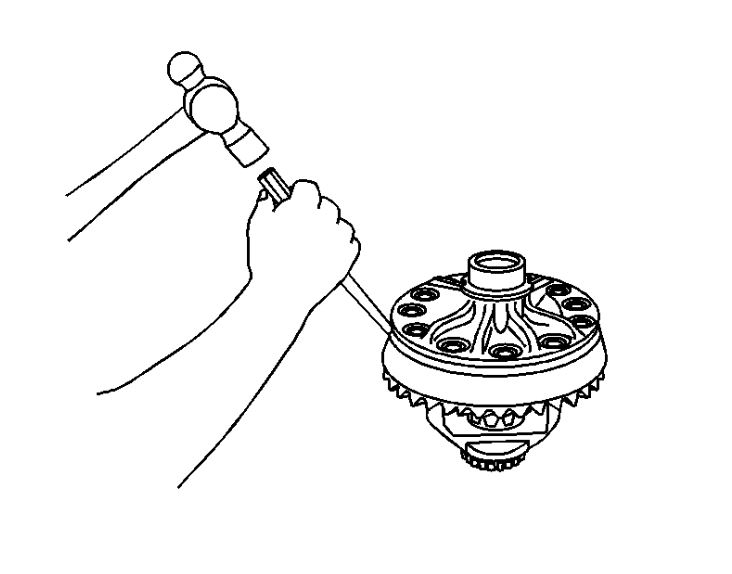
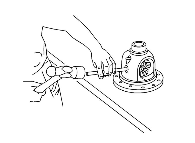
5. Remove the pinion shaft by performing the following steps:
1. Place a brass drift onto the end of the pinion shaft with the pilot hole.
2. Drive the pinion shaft through the differential case using a hammer and the brass drift.
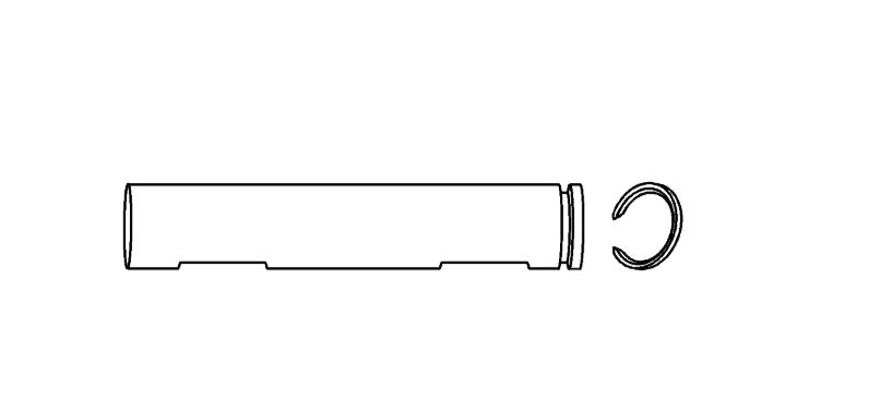
imageOpen In New TabZoom/Print
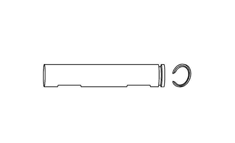
6. Remove the retaining ring from the pinion shaft. Discard the retaining ring.
imageOpen In New TabZoom/Print
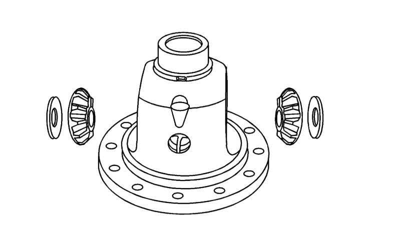
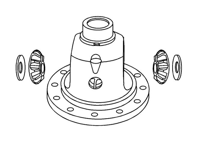
7. Remove the differential pinion gears and the pinion gear thrust washers by rolling the gears out through the differential case opening.
8. Remove the differential side gears and the thrust washers. Mark the pinion gears top and bottom and the differential side gears left and right.
Assembly Procedure
imageOpen In New TabZoom/Print
1. Install the new retaining onto the pinion shaft.
2. Lubricate the pinion and side gears using axle lubricant. Use the proper fluid. Refer to Fluid and Lubricant Recommendations.
3. Install the differential side gear thrust washers to the differential side gears.
4. Install the differential side gears and thrust washers into the differential case.If the same differential side gears and the thrust washers are being used, install the gears and the thrust washers to their original locations.
imageOpen In New TabZoom/Print
5. Install the differential pinion gears and the thrust washers by performing the following steps:
1. Install the thrust washers to the pinion gears.
2. Position one of the pinion gears with the thrust washer between the differential side gears.If the same differential side gears and the thrust washers are being used, install the gears and the thrust washers to their original locations.
3. Install the second pinion gear with the thrust washer between the differential side gears directly opposite of the first gear.
4. Rotate the differential side gears until the pinion gears and the thrust washers are directly opposite the opening in the differential case.
imageOpen In New TabZoom/Print
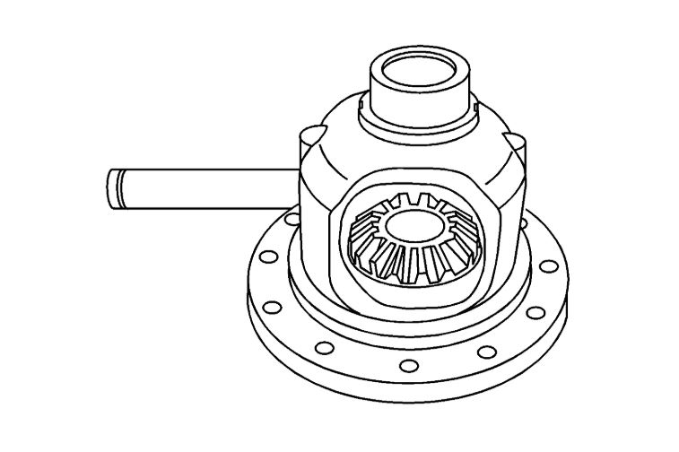
6. Install the pinion shaft into the differential case by performing the following steps:
1. Insert the side of the pinion shaft with the pilot hole into the differential case.
2. Slide the pinion shaft through the differential case until the retaining ring is against the differential case.
3. Carefully drive the pinion shaft into the differential case using a hammer and a brass drift. Ensure that the pinion shaft retaining ring is seated in the channel within the differential case.
imageOpen In New TabZoom/Print
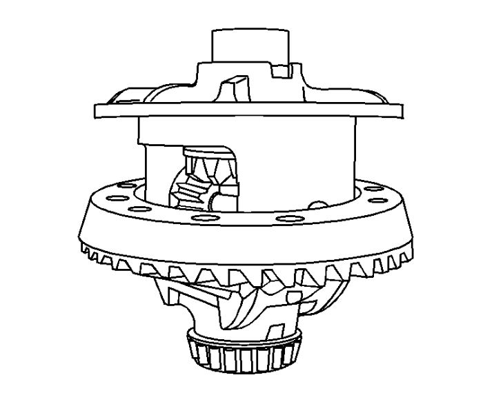
7. Install the ring gear to the differential case.
Important: The mating surface of the ring gear and the differential case must be clean and free of burrs before installing the ring gear.
imageOpen In New TabZoom/Print
8. Install the new ring gear bolts. Hand start each bolt in ensure the ring gear is properly installed to the differential case.
Notice: Refer to Fastener Notice in Service Precautions.
Important: The ring gear bolts have right-hand threads.
9. Tighten the ring gear bolts.
Tighten the bolts alternately and in stages, gradually pulling the ring gear onto the differential case.
Tighten the ring gear bolts in sequence to 237 Nm (175 lb ft).
imageOpen In New TabZoom/Print
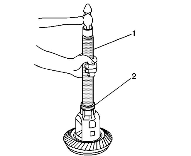
10. Install the differential side bearings by performing the following steps:
1. In order to protect the differential case, install the J 8107-5 in the case on the side opposite the bearing installation.
2. Install the J 44420 (2) and the J 8092 (1) onto the differential case bearing as shown.
3. Drive the bearing onto the case using the J 44420 and the J 8092.
Images (Click to enlarge)
Feb 7, 2020 at 4:33 PM