Welcome to 2CarPros.
I hate to say it, but I have a feeling the timing was off a tooth or two.
Here are the directions specific to your vehicle. All attached pictures correlate with these directions for removal and replacement of the belt. This is the first thing I would check. I added everything in case there was something you needed.
___________________________________________
REMOVAL AND REPLACEMENT
TIMING BELT
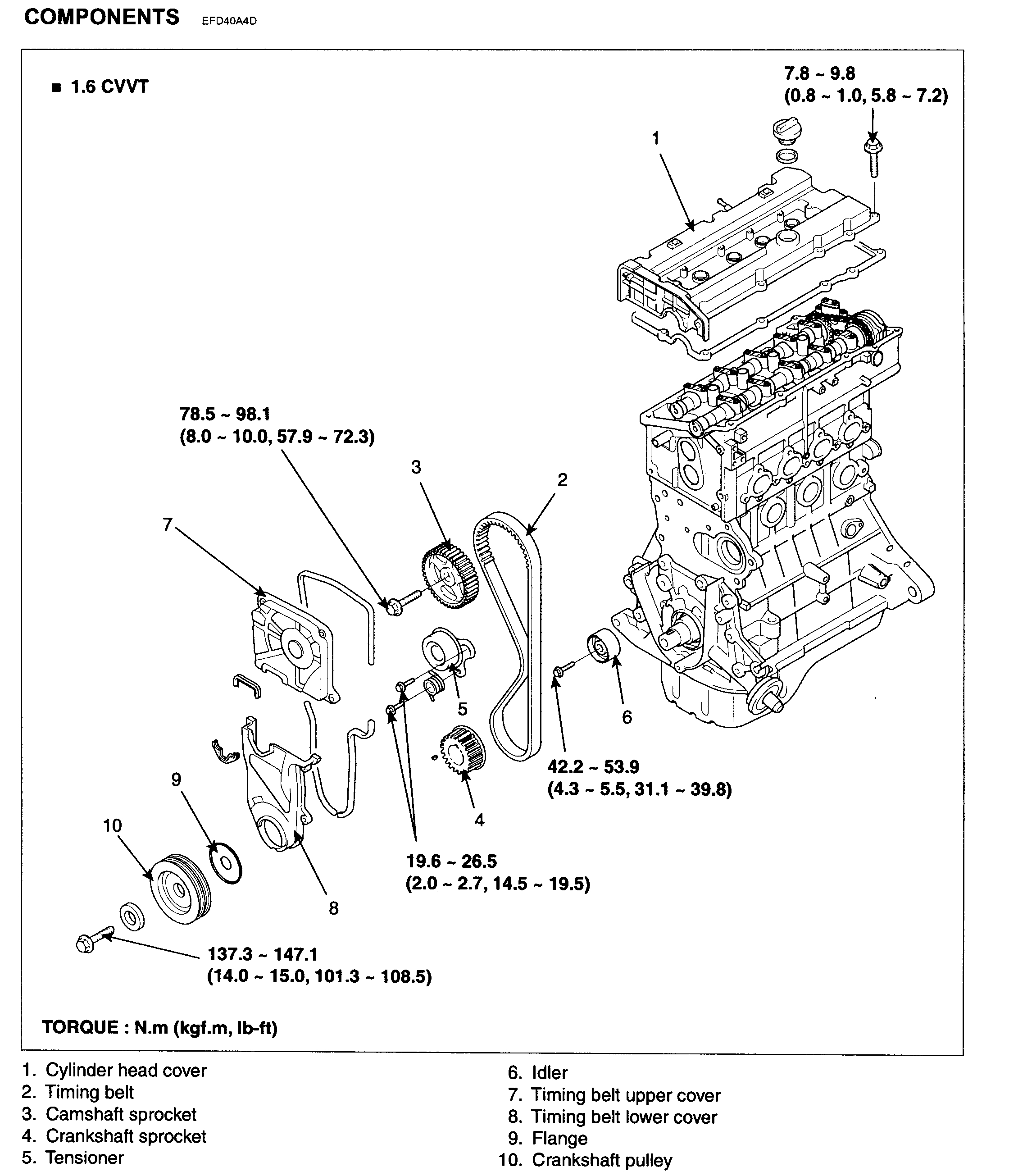
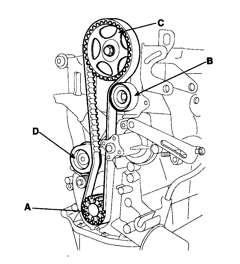
COMPONENTS
pic 1
REMOVAL
Engine removal is not required for this procedure.
1. Remove the engine cover.
2. Remove the RH front wheel.
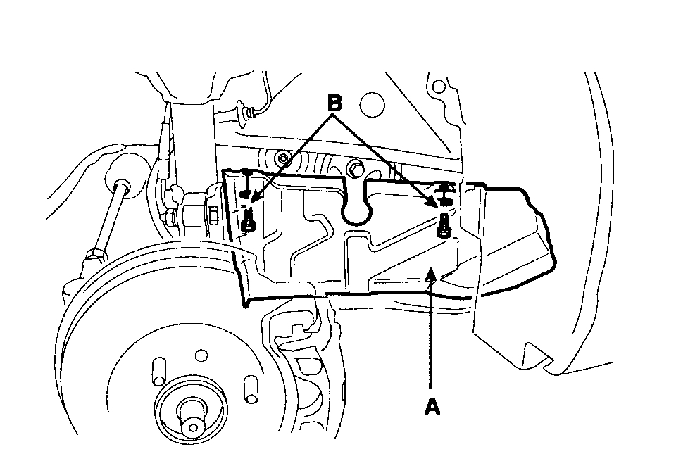
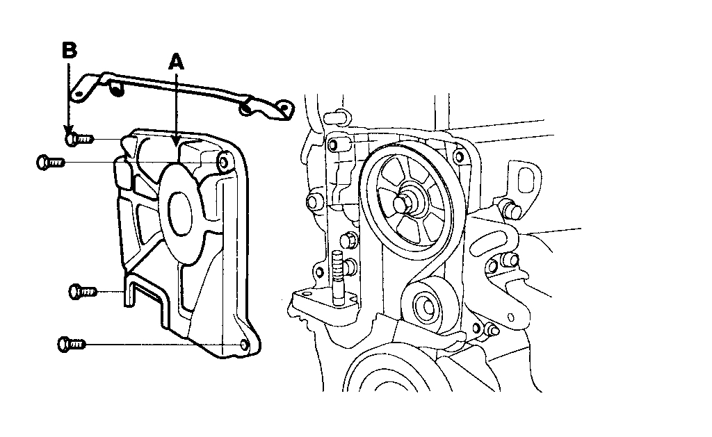
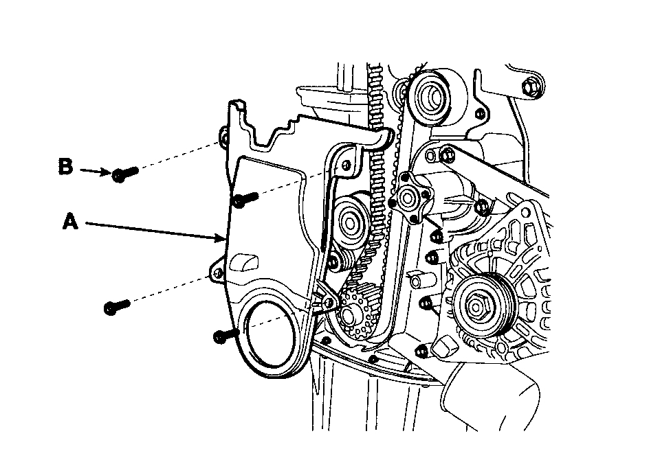
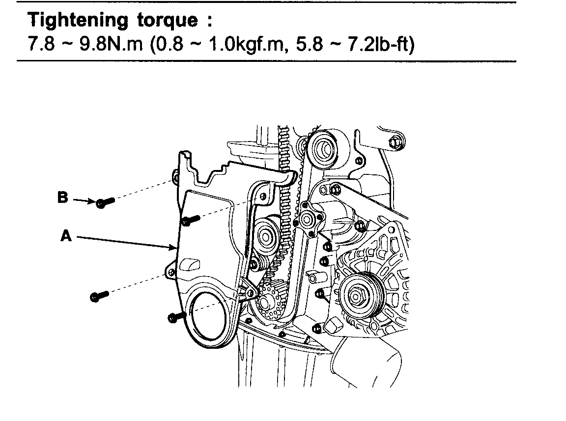
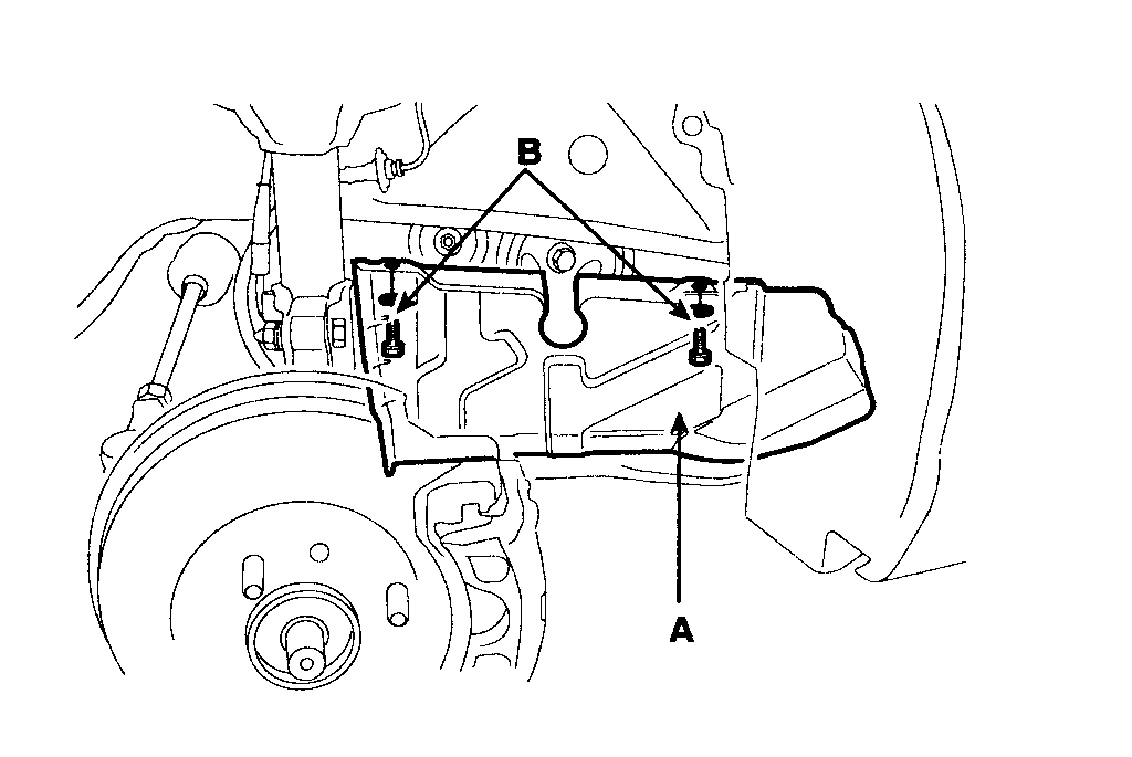
3. Remove the 2 bolts(B) and RH side cover(A).
pic 2
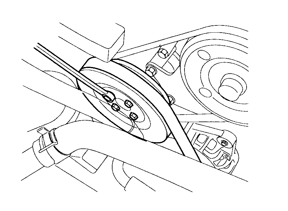
4. Temporarily loosen the water pump pulley bolts.
pic 3
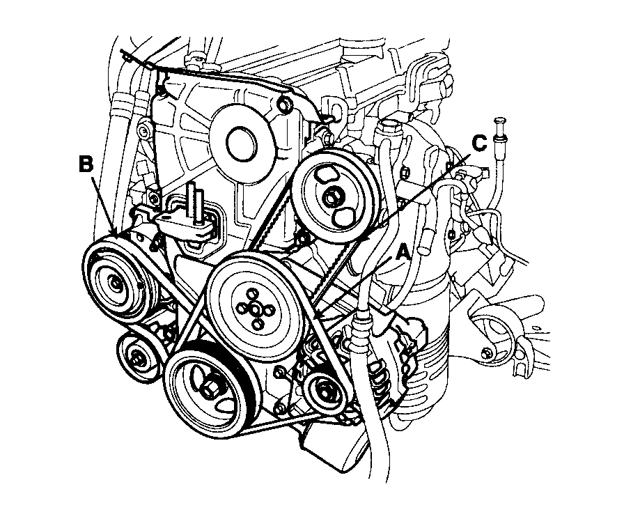
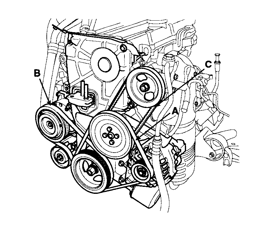
5. Remove the alternator drive belt(A).
pic 4
6. Remove the air conditioner compressor drive belt(B).
7. Remove the power steering pump drive belt(C).
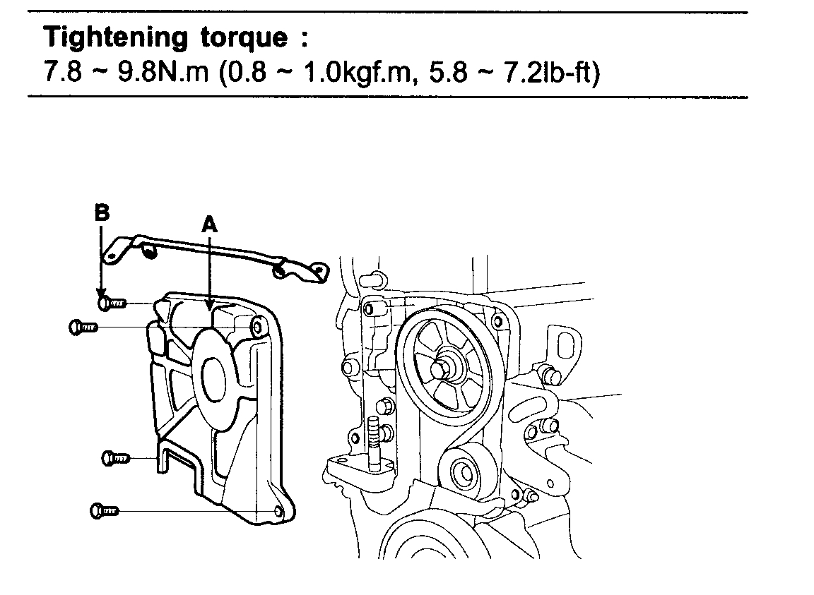
8. Remove the 4 bolts and water pump pulley.
9. Remove the 4 bolts(B) and timing belt upper cover(A).
pic 5
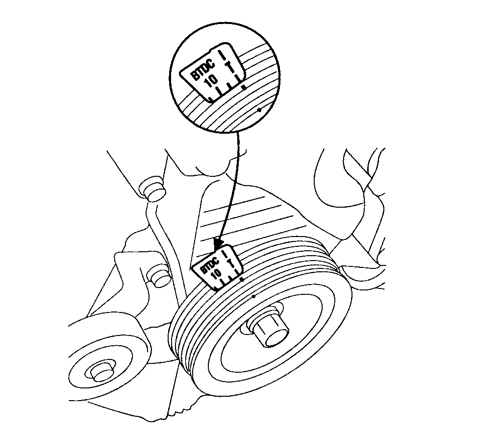
10. Turn the crankshaft pulley, and align its groove with timing mark "T" of the timing belt cover. Check that the timing mark of camshaft sprocket is aligned with the timing mark of cylinder head cover. (No.1 cylinder compression TDC position)
pic 6
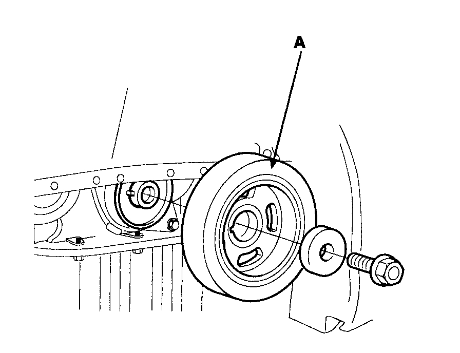
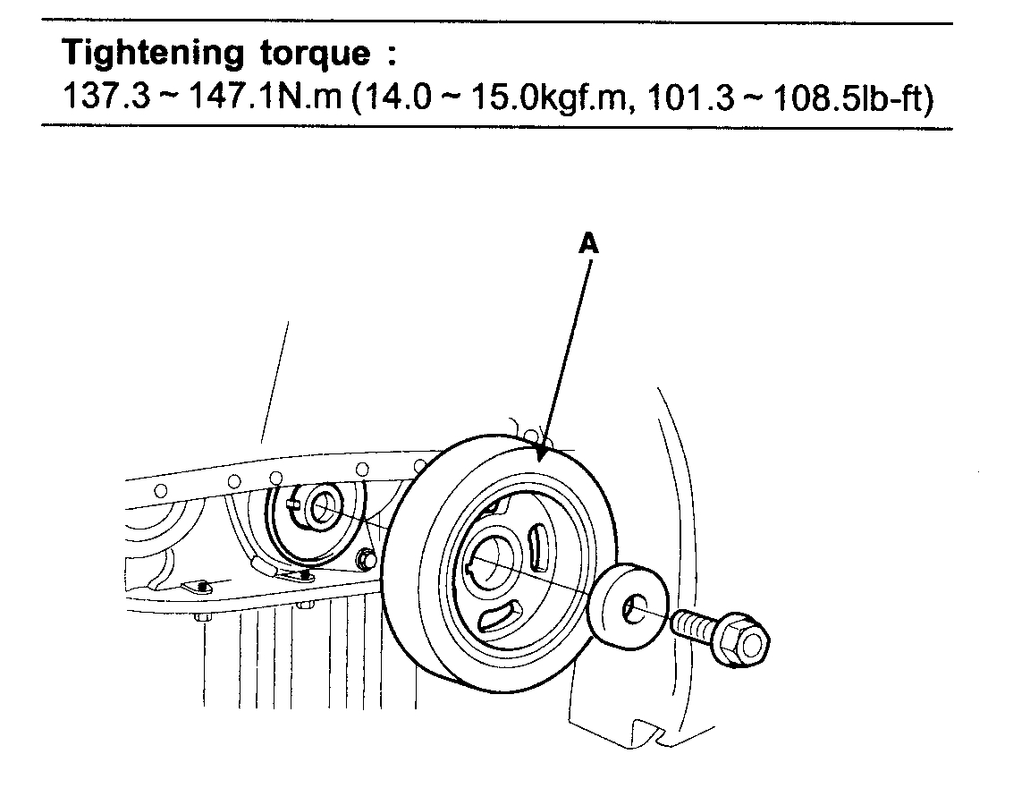
11. Remove the crankshaft pulley bolt and crankshaft pulley(A).
pic 7
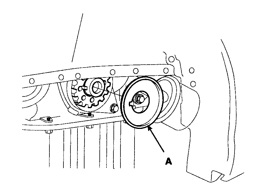
12. Remove the crankshaft flange(A).
pic 8
13. Remove the 4 bolts(B) and timing belt lower cover(A).
pic 9
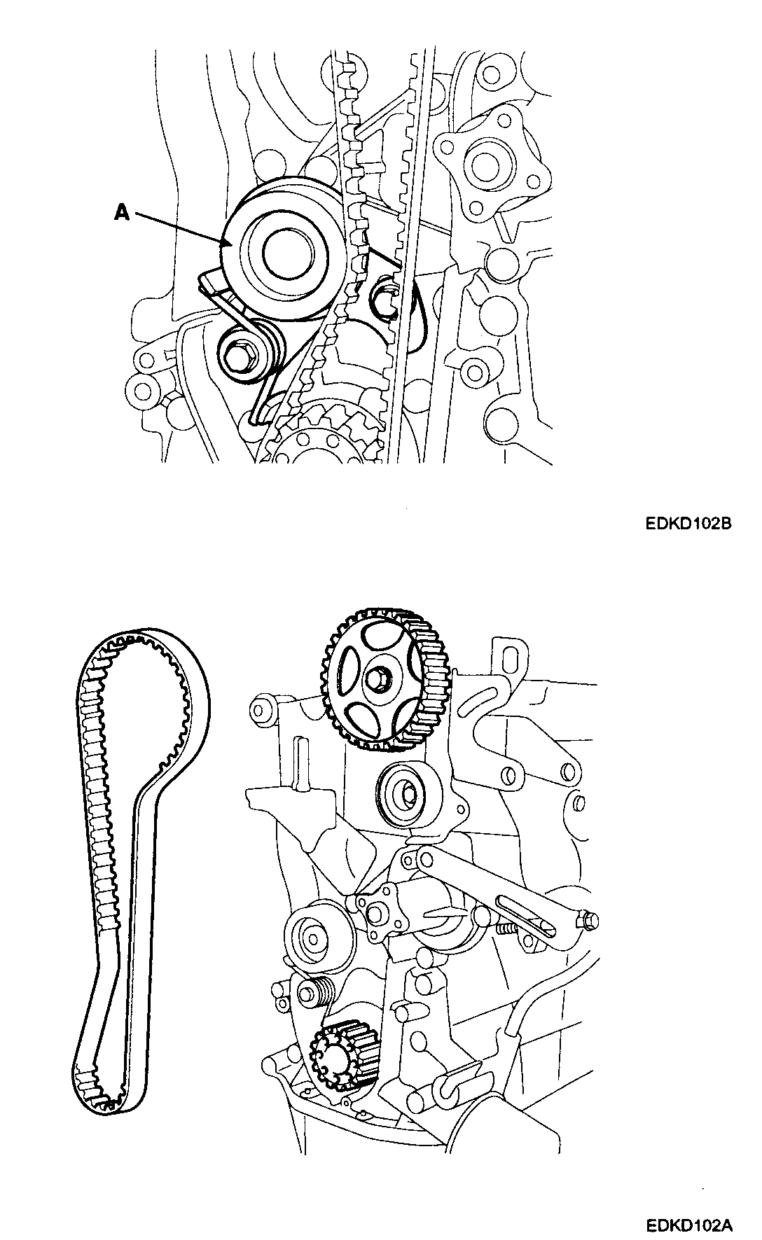
14. Remove the timing belt tensioner(A) and timing belt.
pic 10
NOTE: If the timing belt reused, make an arrow indicating the turning direction to make sure that the belt is reinstalled in the same direction as before.
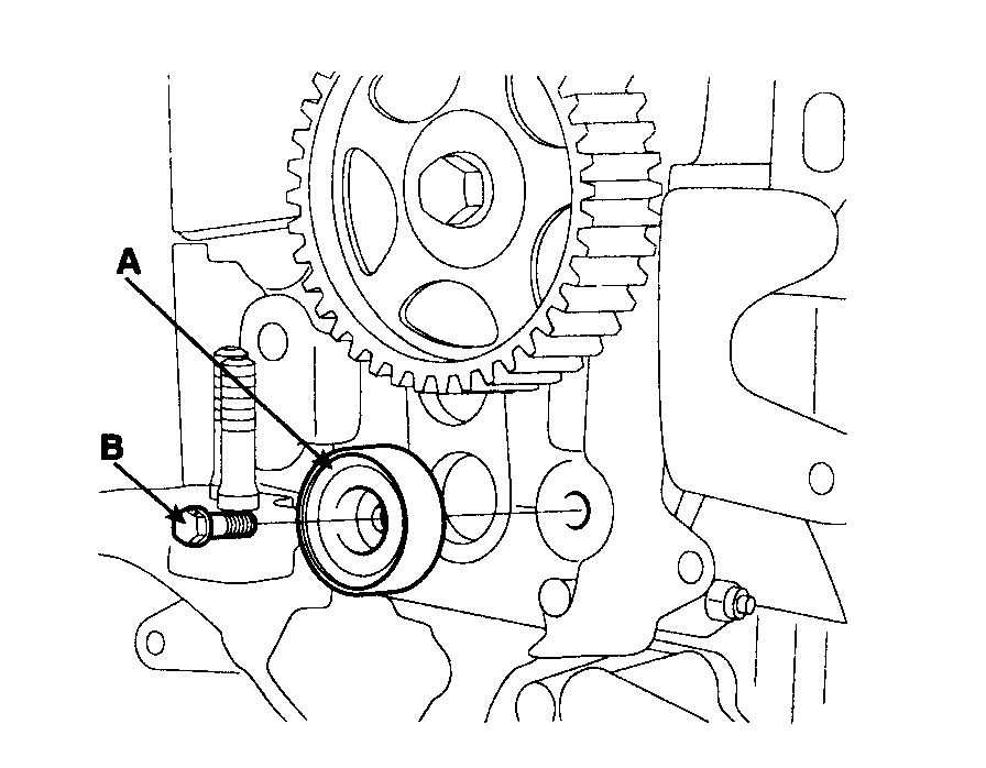
15. Remove the bolt(B) and timing belt idler(A).
pic 11
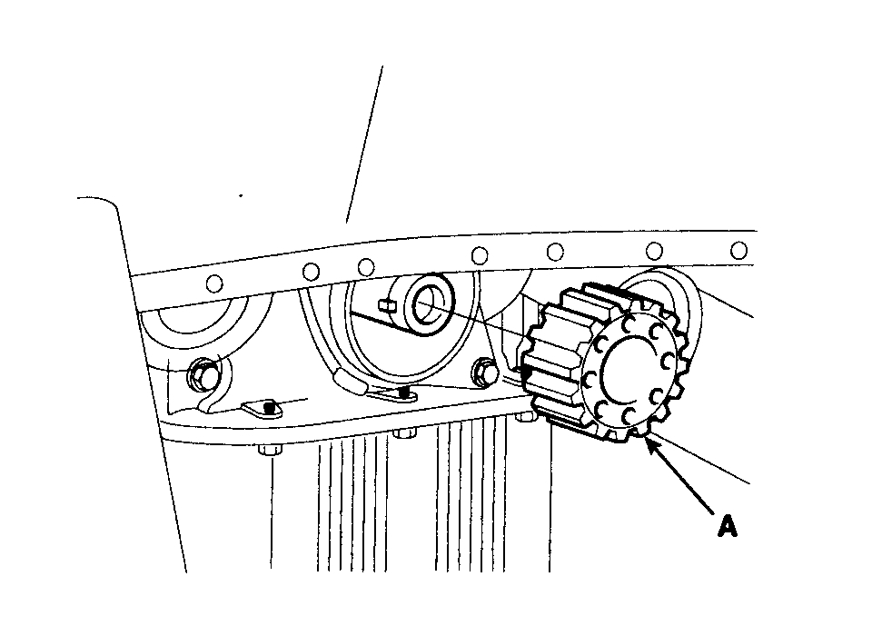
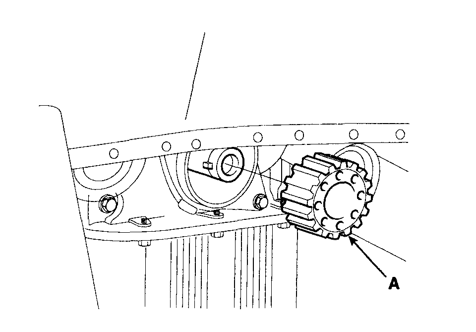
16. Remove the crankshaft sprocket(A).
pic 12
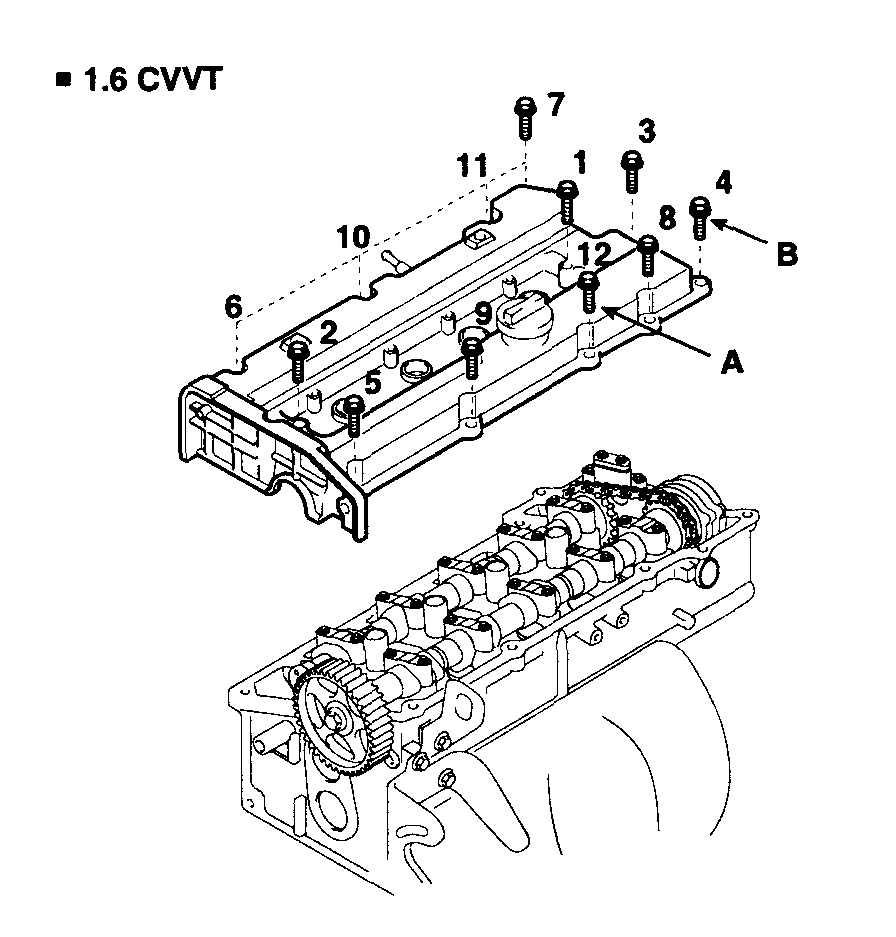
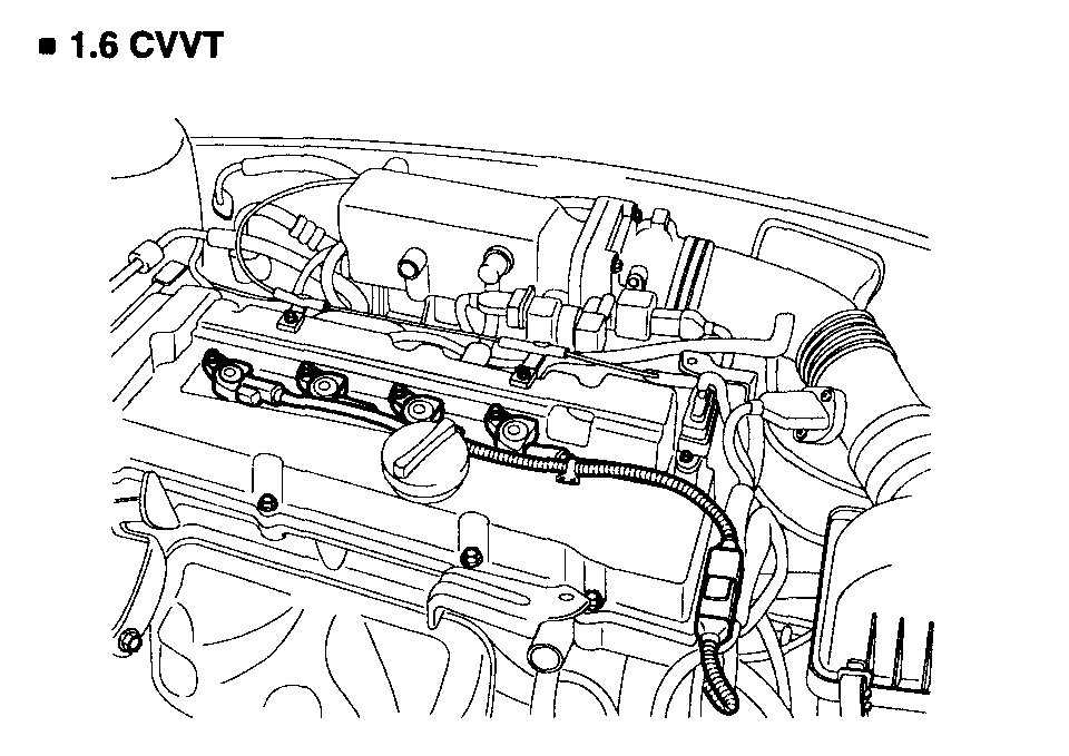
17. Remove the cylinder head cover.
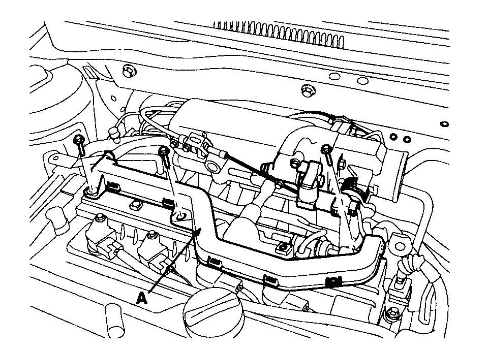
1) Remove the wire harness bracket(A).
pic 13
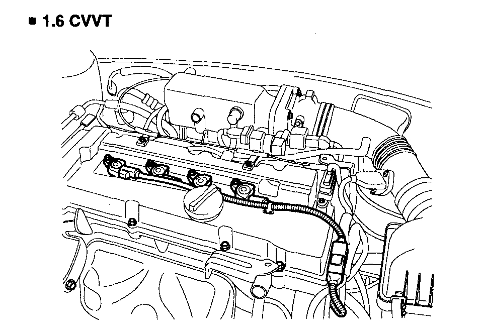
2) Remove the ignition coil.
pic 14
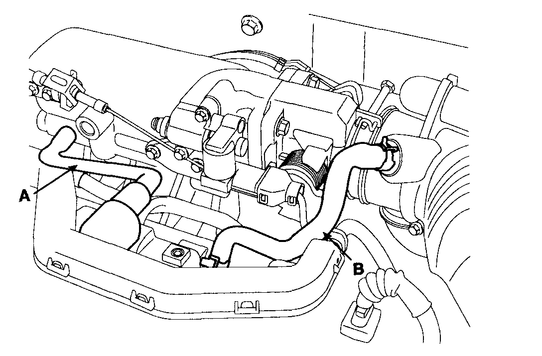
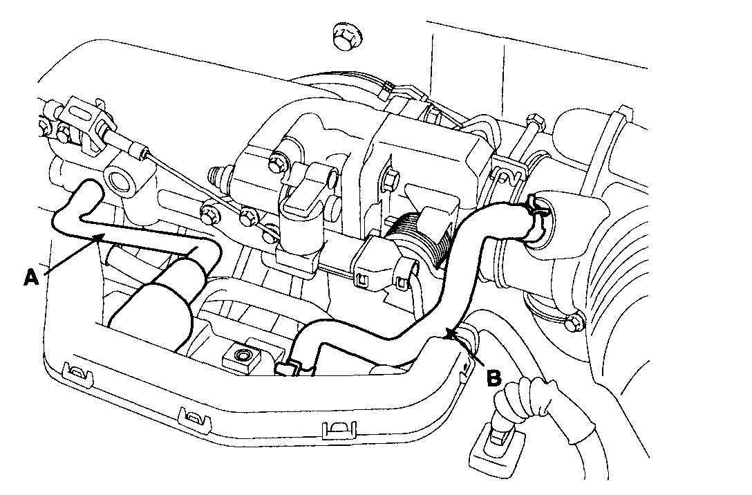
3) Remove the PCV (Positive Crankcase Ventilation) hose(A) and the breather hose(B) from the cylinder head cover.
pic 15
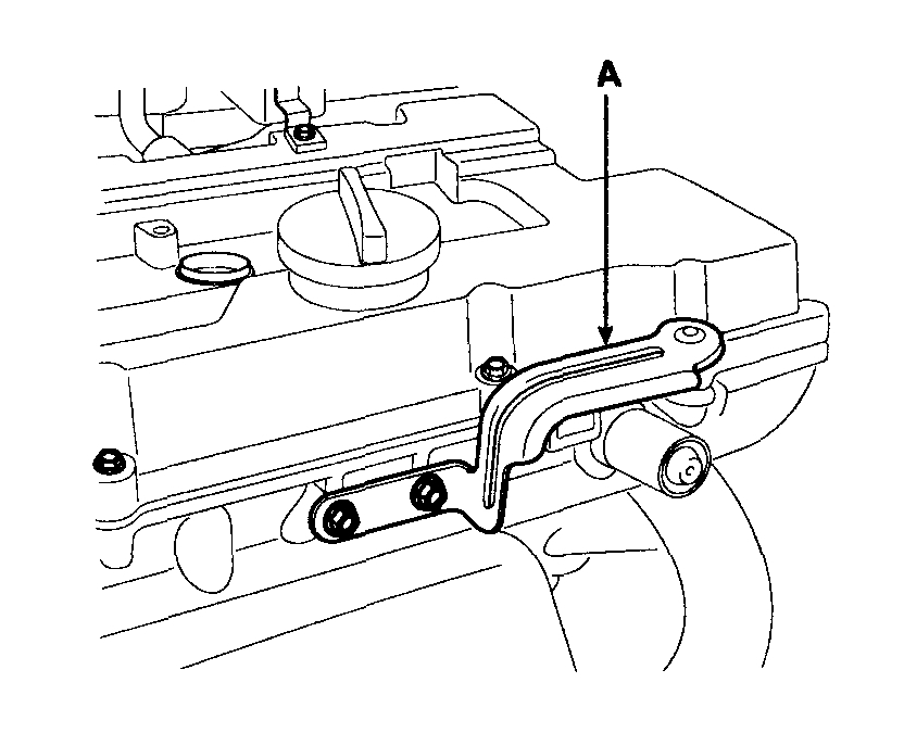
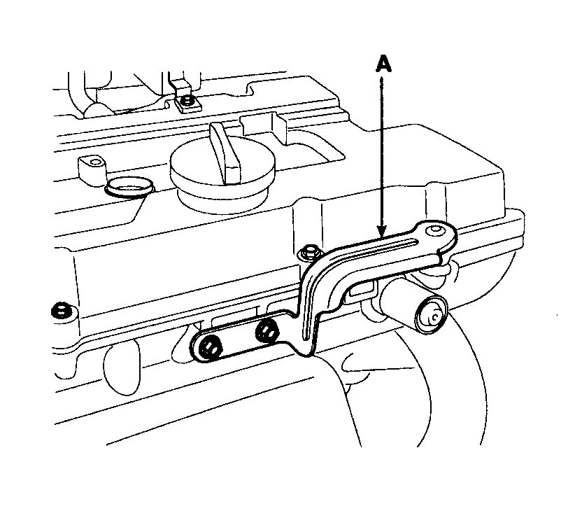
4) Remove the engine cover bracket(A).
pic 16
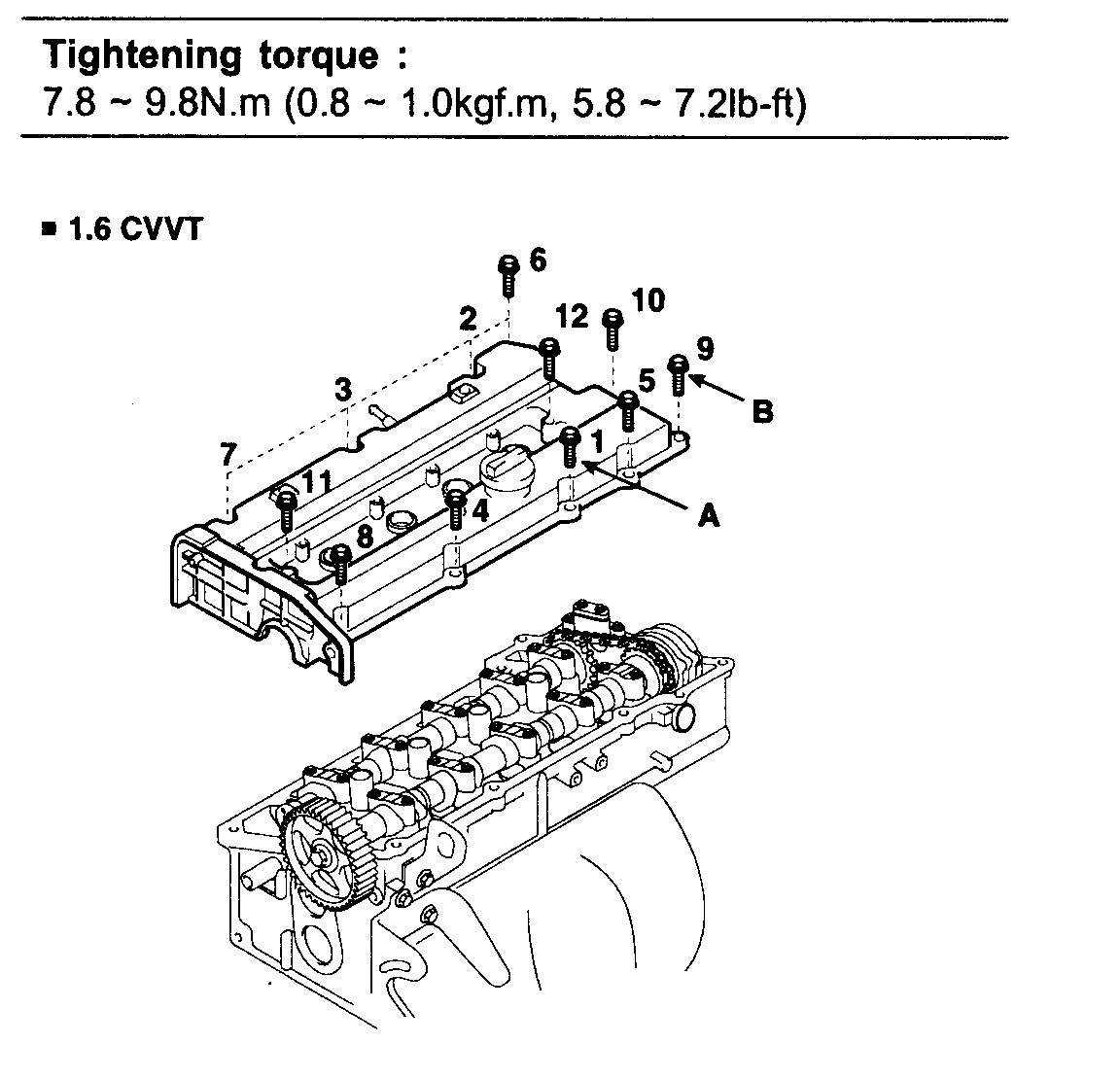
5) Loosen the cylinder head cover bolts(B) and then remove the cover(A) and gasket.
pic 17
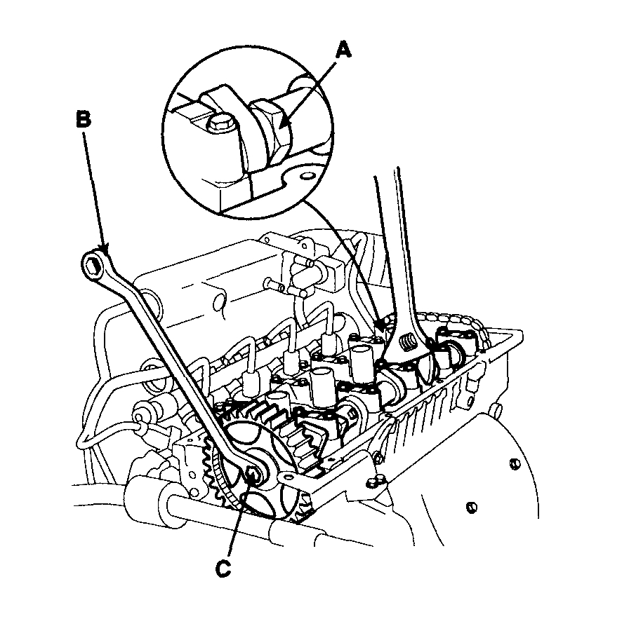
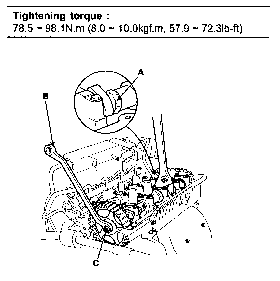
18. Remove the camshaft sprocket.
1) Hold the portion(A) of the camshaft with a hexagonal wrench, and remove the bolt(C) with a wrench(B) and remove the camshaft sprocket.
pic 18
CAUTION: Be careful not to damage the cylinder head and valve lifter with the wrench.
INSPECTION
TIMING BELT
1. Check the belt for oil or dust deposits.
Replace, if necessary.
Small deposits should be wiped away with a dry cloth or paper. Do not clean with solvent.
2. When the engine is overhauled or belt tension adjusted, check the belt carefully. If any of the following flaws are evident, replace the belt.
NOTE:
^ Do not bend, twist or turn the timing belt inside out.
^ Do not allow timing belt to come into contact with oil, water and steam.
3. Inspect the belt closely. If the following problems are evident, replace the belt with a new one.
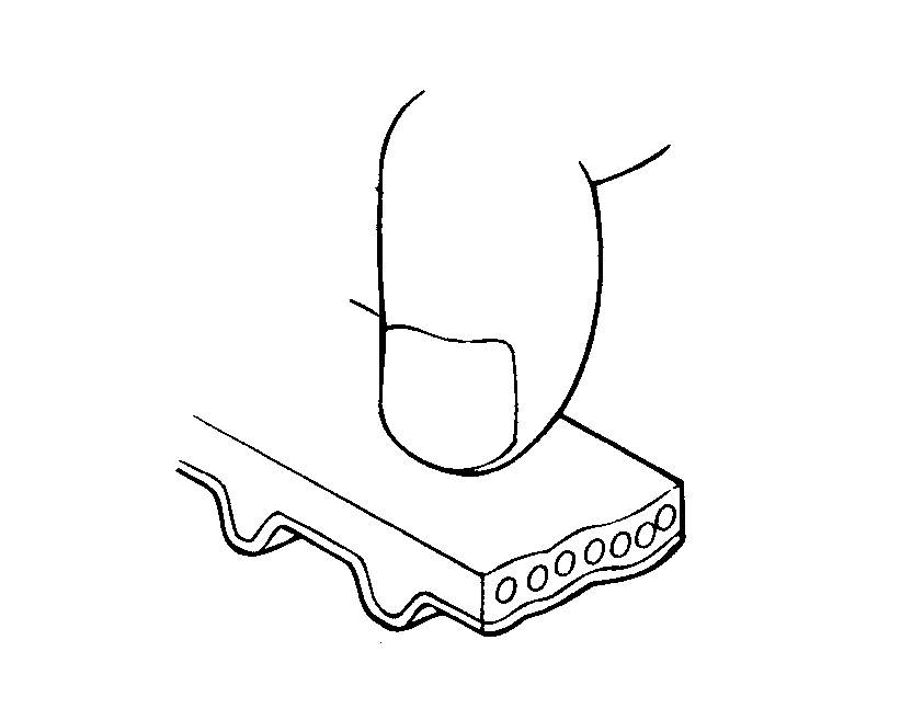
1) Hardened back surface of rubber.
Back surface is glossy, non-elastic and so hard that when the nail of your finger is pressed into it, no mark is produced.
pic 19
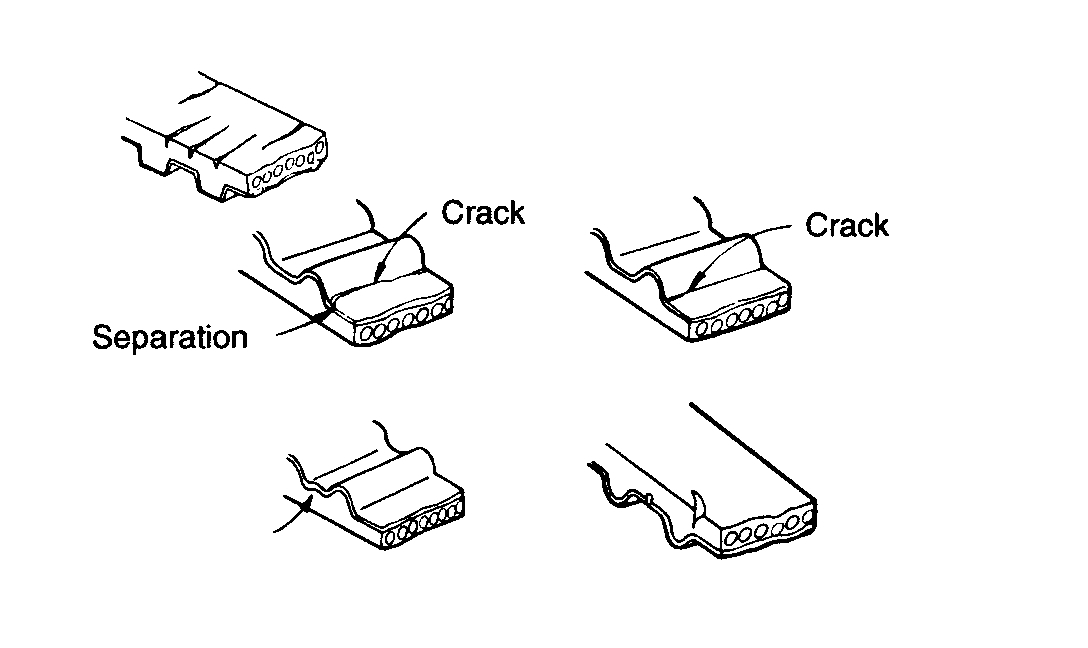
2) Cracked back surface of rubber.
pic 20
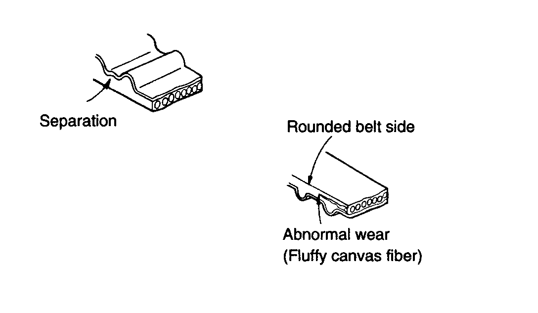
3) Side of belt is badly worn.
NOTE: A belt in good condition should have clear-cut sides as if it were cut with a sharp knife.
pic 21
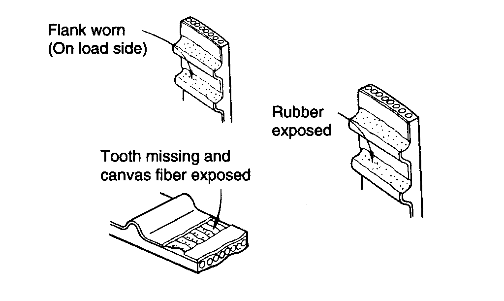
4) Teeth are badly worn out.
Initial stage: Canvas on load side of the tooth flank worn (fluffy canvas fibers, rubber gone, color changed to white, and unclear canvas texture)
Last stage: Canvas on the load side of the tooth flank worn down and rubber exposed (tooth width reduced).
5) Missing tooth.
pic 22
SPROCKETS, TENSIONER, IDLER
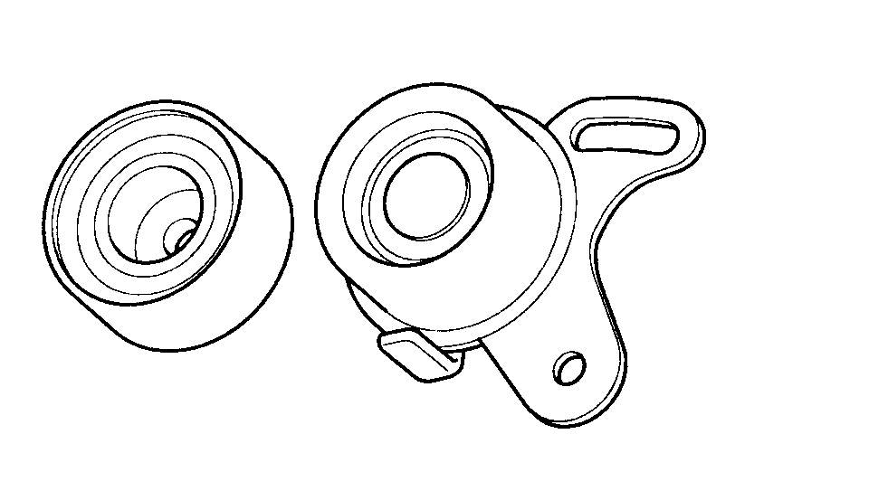
1. Check the camshaft sprocket, crankshaft sprocket, tensioner pulley and idler pulley for abnormal wear, cracks, or damage. Replace as necessary.
2. Inspect the tensioner pulley and the idler pulley for easy and smooth rotation and check for play or noise. Replace as necessary.
pic 23
3. Replace the pulley if there is a grease leak from its bearing.
INSTALLATION
1. Install the camshaft sprocket and tighten the bolt to the specified torque.
1) Temporarily install the camshaft sprocket bolt(C).
2) Hold the portion(A) of the camshaft with a hexagonal wrench, and tighten the bolt(C) with a wrench(B).
pic 24
2. Install the cylinder head cover.
1) Install the cylinder head cover(A) and bolts(B).
pic 25
2) Install the engine cover bracket(A).
pic 26
3) Install the PCV(Positive Crankcase Ventilation) hose(A) and breather hose(B) to the cylinder head cover.
pic 27
4) Install the ignition coil.
pic 28
3. Install the crankshaft sprocket(A).
pic 29
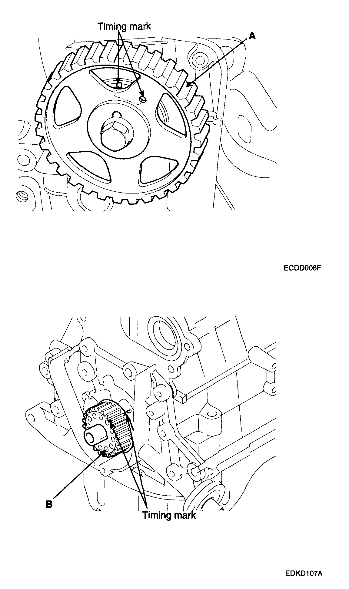
4. Align the timing marks of the camshaft sprocket(A) and crankshaft sprocket(B) with the No.1 piston placed at top dead center and its compression stroke.
pic 30
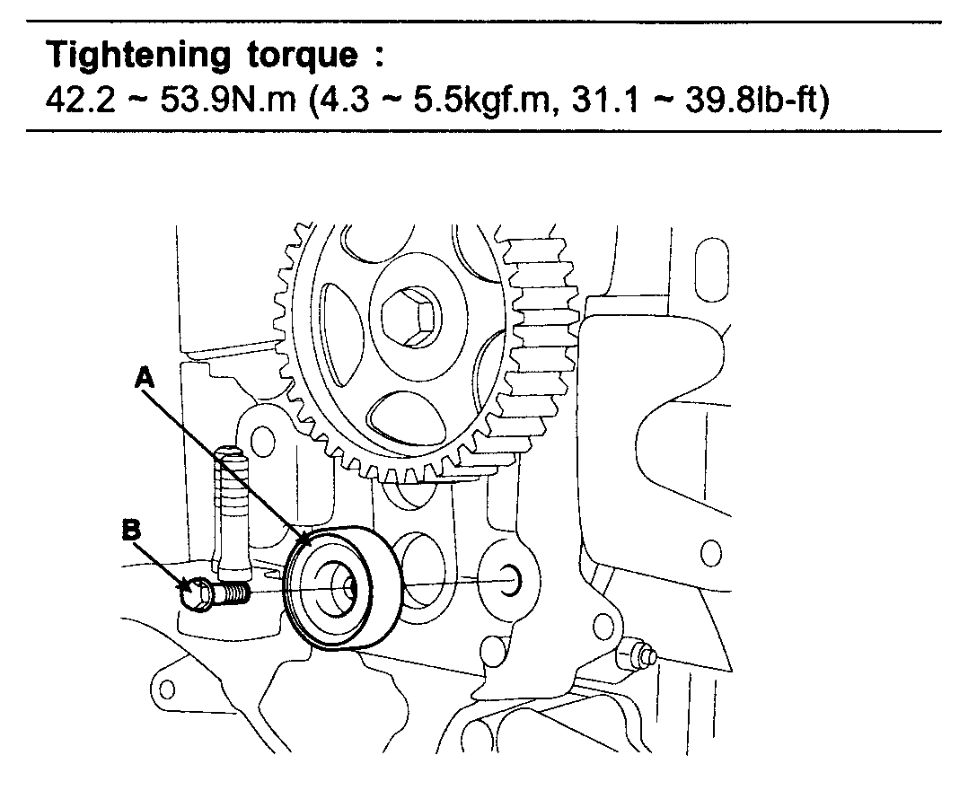
5. Install the idler pulley(A) and tighten the bolt(B) to the specified torque.
pic 31
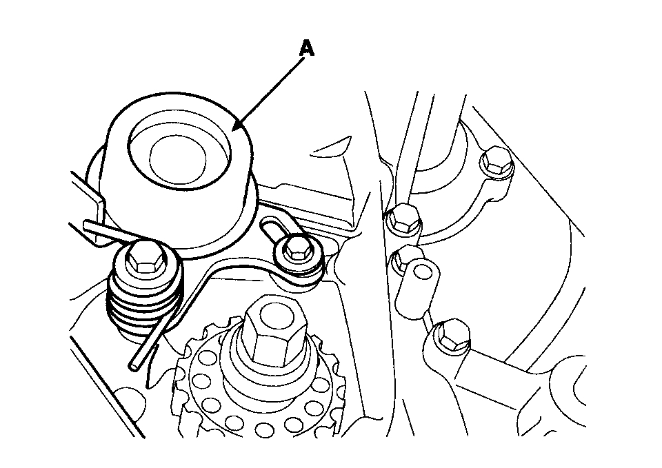
6. Temporarily install the timing belt tensioner(A).
pic 32
7. Install the belt so as not give slack at each center of shaft. Use the following order when installing timing belt.
Crankshaft sprocket(A) >idler pulley(B) >camshaft sprocket(C) >timing belt tensioner(D).
pic 33
8. Adjust the timing belt tension.
1) Loosen the tensioner pulley mounting bolt and apply tension to the timing belt.
pic 34
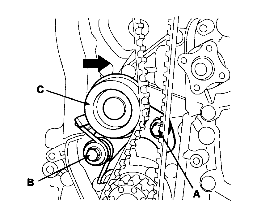
2) After checking the alignment between each sprocket and each timing belt tooth, tighten the mounting bolt (A) and (B) one by one.
Tightening torque: 19.6 - 26.5N.m (2.0 - 2.7kgf.m, 14.5 - 19.5lb-ft)
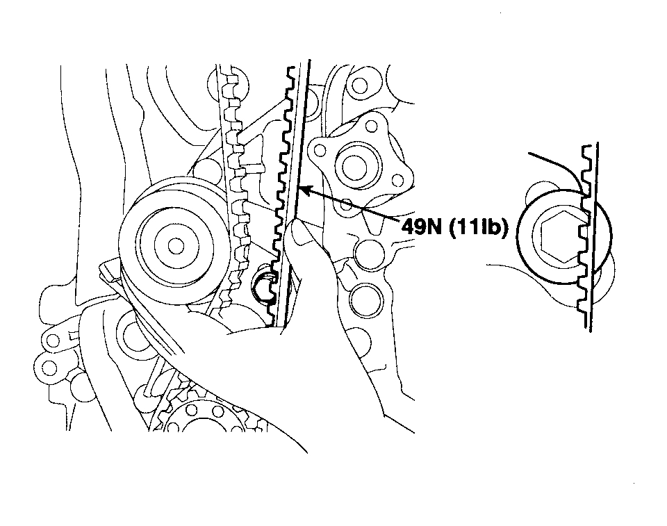
3) Then recheck the belt tension.
Verify that when the tensioner and the tension side of the timing belt are pushed in horizontally with a moderate force [approximately. 49N (11lb)], the timing belt cog end is aprox. 1/2 of the tensioner mounting bolt head radius (across flats) away from the bolt head center.
pic 35
4) Timing belt tension measuring procedure (by a sonic tension gage)
Rotate crankshaft in clockwise direction to set 1st piston on top dead center (TDC) and rotate crankshaft in counterclockwise to 90° then measure the belt tension in the middle of tension side span (in arrow direction of above illustration) by free vibration method.
CAUTION: Avoid rotating the crankshaft in a counter clockwise direction. Engine damage could occur.
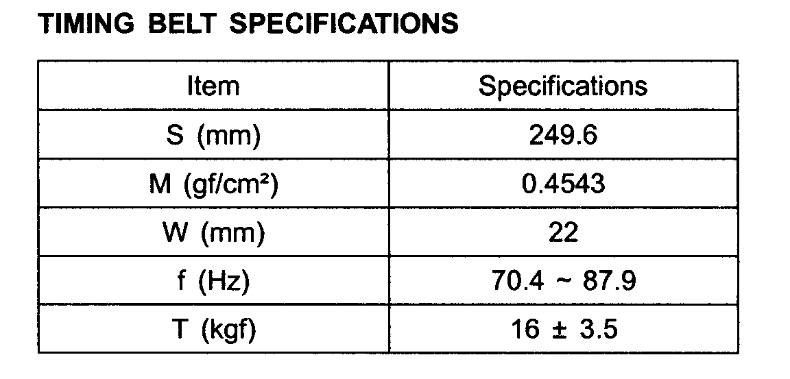
Conversion equation of frequency into tension: T = (4 / 9.8) x S2 x M x W x f2 / 100000000
S: Measured belt span (mm)
M: Unit weight of belt (gf/cm2)
W: Belt width (mm)
f: Transverse natural frequency of belt (Hz)
TIMING BELT SPECIFICATIONS
pic 36
9. Turn the crankshaft two turns in the operating direction (clockwise) and realign crankshaft sprocket and camshaft sprocket timing mark.
10. Install the timing belt lower cover(A) with 5bolts(B).
pic 39
11. Install the flange and crankshaft pulley(A), and then tighten crankshaft pulley bolt. Make sure that crankshaft sprocket pin fits the small hole in the pulley.
pic 40
12. Install the timing belt upper cover(A) with 4 bolts(B).
pic 41
13. Install the water pump pulley and 4 bolts.
14. Install the power steering pump drive belt(C).
pic 42
15. Install the air conditioner compressor drive belt(B).
16. Install the alternator drive belt(A).
17. Install the RH side cover(A) with 2 bolts(B).
pic 43
18. Install the RH front wheel.
Tightening torque: 88.3 - 98.1N.m (9.0 - 10.0kgf.m, 65.1 - 72.3lb-ft)
19. Install the engine cover with bolts.
Tightening torque: 7.8 - 11.8N.m (0.8 - 1.2kgf.m, 5.8 - 8.7lb-ft)
__________________________________
I hope this helps.
Take care,
Joe
Images (Click to enlarge)
Apr 20, 2019 at 9:57 PM