U have auomatic lights
and if so
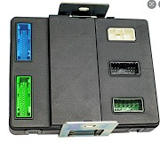
u need to hook scanner and read BCM code and data
BODY CONTROL COMPUTER - TESTS -1999 Plymouth Grand Voyager
Page 1 of 1
NOTE: For connector terminal identification and wiring diagrams, see BODY CONTROL COMPUTER - INTRODUCTION article. Perform VERIFICATION TEST after each repair.
CAUTION:Always turn ignition switch to OFF position prior to disconnecting or connecting any module connector.
AUTOMATIC HEADLIGHTS WILL NOT TURN OFF
1. Using scan tool, select BODY CONTROL MODULE. If scan tool displays NO RESPONSE or CCD BUS FAILURE, go to appropriate VEHICLE COMMUNICATIONS article. If scan tool does not display NO RESPONSE or CCD BUS FAILURE, go to next step.
2. Using scan tool, select POWERTRAIN CONTROL MODULE. If scan tool displays NO RESPONSE or CCD BUS FAILURE, go to appropriate VEHICLE COMMUNICATIONS article. If scan tool does not display NO RESPONSE or CCD BUS FAILURE, go to next step.
3. Using scan tool, select BODY, BODY COMPUTER, then SENSORS. Read AUTO HEADLAMP SENS VOLTS. If voltage reading is 0.6-4.8 volts, replace Body Control Module (BCM). BCM is located with junction block under driver's side instrument panel.. If voltage reading is not 0.6-4.8 volts, go to next step.
4. Disconnect BCM "B" connector. Connect jumper wire between ground and BCM "B" connector terminal No. 51 (White/Light Green wire). Disconnect interior electrochromic mirror connector. Using external ohmmeter, measure resistance between ground and terminal No. 7 (White/Light Green wire) on mirror harness connector. If resistance is less than 5 ohms, go to next step. If resistance is 5 ohms or more, repair open White/Light Green wire.
5. Remove jumper wire. Using external ohmmeter, measure resistance between ground and interior electrochromic mirror connector terminal No.
7 (White/Light Green wire). If resistance is less than 1000 ohms, repair White/Light Green wire for short to ground. If resistance is 1000 ohms or more, replace interior electrochromic mirror.
8/2/2008
Saturday, August 2nd, 2008 AT 10:17 PM


