PCM pinout

Tiny
AVIONICS EAGLE
  • MEMBER
  • 2014 DODGE CARAVAN
  • 3.6L
  • 157,000 MILES
I just need a PCM pinout for my exact vehicle. Thanks
Saturday, November 14th, 2020 AT 10:55 AM

16 Replies

Tiny
KASEKENNY
  • MECHANIC
  • 18,907 POSTS
Attached are the pinouts for C1 and 2 of the PCM. Let us know if you have more questions. Thanks
Was this
answer
helpful?
Yes
No
+3
Saturday, November 14th, 2020 AT 11:07 AM
Tiny
AVIONICS EAGLE
  • MEMBER
  • 12 POSTS
Thank you! That helps a lot. I'm trying to fix the alternator control circuit to provide battery charging, but I can't seem to find the correct circuit diagrams.
Was this
answer
helpful?
Yes
No
Saturday, November 14th, 2020 AT 11:49 AM
Tiny
KASEKENNY
  • MECHANIC
  • 18,907 POSTS
You are welcome. I think there was another post on this last night as this sounds familiar. If this is the same, let us know how you make out on just one of these posts but if not, here is the diagram. More then likely you have an issue on the field control circuit. That is not uncommon on these vehicles. This circuit is a pulse width signal and when there is resistance on it, the alternator doesn't operate properly. Take a look at the attachments for more detail.
Was this
answer
helpful?
Yes
No
+1
Sunday, November 15th, 2020 AT 9:49 AM
Tiny
AVIONICS EAGLE
  • MEMBER
  • 12 POSTS
Thanks for your help! The history is: 1) The battery drained out and read 10.5Vdc so I replaced it. 2) The battery read 12.7Vdc running and off, so I removed the alternator and it bench tested good at O'Reillys auto parts. I reinstalled it and still no charging. 3) I checked the wiring from the alternator to the PCM and didn't find anything wrong (alternator pins 1 and 2 checked good (0.2 Ohms) to PCM brown plug pins 2 and 40, and to no other pins). With the PCM plugs removed and the alternator and battery reconnected (read 12.4Vdc), the white plug (now with your info I know that's C1) had solid grounds on pins 49, 50, 51, 52, 53, and 72, and 12.4Vdc on pins 80 and 96. The brown plug (C2) had 12.4Vdc on pin 40, and pin 2 still reads continuity to pin 2 on the alternator (no voltage). So I ordered a PCM. I'll continue in the next reply.
Was this
answer
helpful?
Yes
No
Monday, November 16th, 2020 AT 9:29 AM
Tiny
AVIONICS EAGLE
  • MEMBER
  • 12 POSTS
4) I got 2 bad PCM's on line, pre-programmed to vin, but had other problems. One DID make the alternator work, so I had that one reprogrammed by the dealer. It fixed some problems, but not all. 5) So I got a new Mopar PCM (and programmed) from the dealer. Still not charging, but no new problems. They swore the problem wasn't with their PCM. 6) So I replaced the alternator even though the original bench tested good, and still not charging. Alternator pin 1 reads 2.0 Ohms to ground with engine off and 3mV with engine running, pin 2 reads 12.4Vdc with engine off and 9.4Vdc with engine running. So I replaced the alternator again (thinking it could have been bad from the store) but STILL not charging. The battery gets down to about 11.5Vdc with the engine running before I recharge it to continue troubleshooting. 7) That's when I found your site on line and finally got the right PCM pinout and charging diagram! I'm not convinced that the PCM I got from the dealer is good, but it still could be the alternator wiring to the PCM (I'll recheck the resistance) since the pin 2 voltage drops to 9.4Vdc with the engine running, or the B+ input into C1 pin 96. The bad PCM that does operate the alternator could have bad monitoring, so it would likely over charge the battery. Thanks again for your help!
Was this
answer
helpful?
Yes
No
+1
Monday, November 16th, 2020 AT 10:09 AM
Tiny
AVIONICS EAGLE
  • MEMBER
  • 12 POSTS
Oh yeah, will also check red alternator wiring to battery. Thanks again. Should be back on it today.
Was this
answer
helpful?
Yes
No
Monday, November 16th, 2020 AT 11:57 AM
Tiny
AVIONICS EAGLE
  • MEMBER
  • 12 POSTS
Okay, still no joy.
Rechecked wiring with alternator connected and battery terminals disconnected:
Alt pin 1 to PCM C2 pin 2: 0.1 Ohms,
Alt pin 2 to PCM C2 pin 40: 0.1 Ohms,
Alt pin 1 to gnd: 2.7 Ohms,
(C1 pin 50 = gnd = batt black lead)
Alt pin 2 to gnd: climbs - 2k to above 10k. Just keeps climbing.
With Alt disconnected:
Alt pin 1 to gnd open
Alt pin 2 to gnd open
PCM C1 pin 96 to red batt lead: 0.1 Ohms,
Large red Alt lead to red batt lead: 0.5 to 1.0 Ohm.

I'll have to try again tomorrow.
Was this
answer
helpful?
Yes
No
Monday, November 16th, 2020 AT 2:43 PM
Tiny
AVIONICS EAGLE
  • MEMBER
  • 12 POSTS
Okay, I see it is a problem for the sense line (Alt pin 2) to drop to 9.4Vdc when the engine is running. Your circuit operation description says the Alt output terminal is internally connected to the pin 2 sense output to the PCM. There must be resistance in the alternator output terminal to the battery positive terminal, dropping the 3Vdc
(or the Alt conn socket to the Alt pin 2, but it looked solid).
I should be able to get back on it today.
Thanks so much for the diagram, circuit operation description and PCM pinout. Huge help!
Was this
answer
helpful?
Yes
No
Tuesday, November 17th, 2020 AT 9:58 AM
Tiny
KASEKENNY
  • MECHANIC
  • 18,907 POSTS
Sorry for the delay but I think you found it. You appear to be exactly correct. When you see resistance climb past 10k ohms that is the first sign of high resistance. Then to have a voltage drop of 3 volts is just more confirmation. Thanks for the updates and good work.
Was this
answer
helpful?
Yes
No
Tuesday, November 17th, 2020 AT 5:53 PM
Tiny
AVIONICS EAGLE
  • MEMBER
  • 12 POSTS
Okay, still not solved. I was fooled by resistance readings with the PCM still connected. Recharged battery, disconnected PCM C1 and C2, and reconnected the battery:
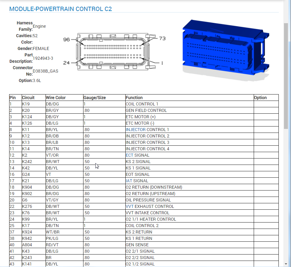
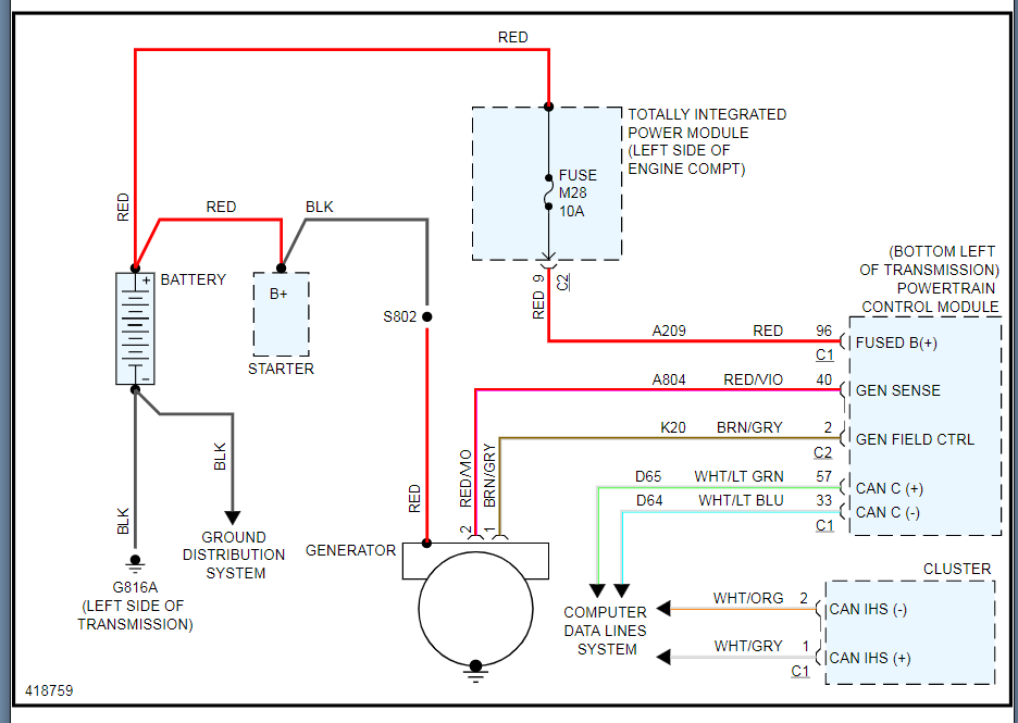
Alt pin1 to C2 pin 2: 0.1 Ohms.
With 12.7Vdc put on Alt pin1, C2 pin2 lights the test light.
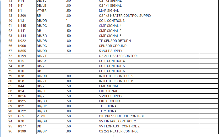
Alt pin2 to C2 pin40. 0.1 Ohms.
12.7Vdc to Alt pin2, C2 pin40 lights the test light.
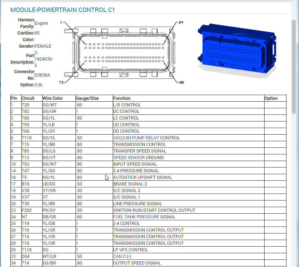
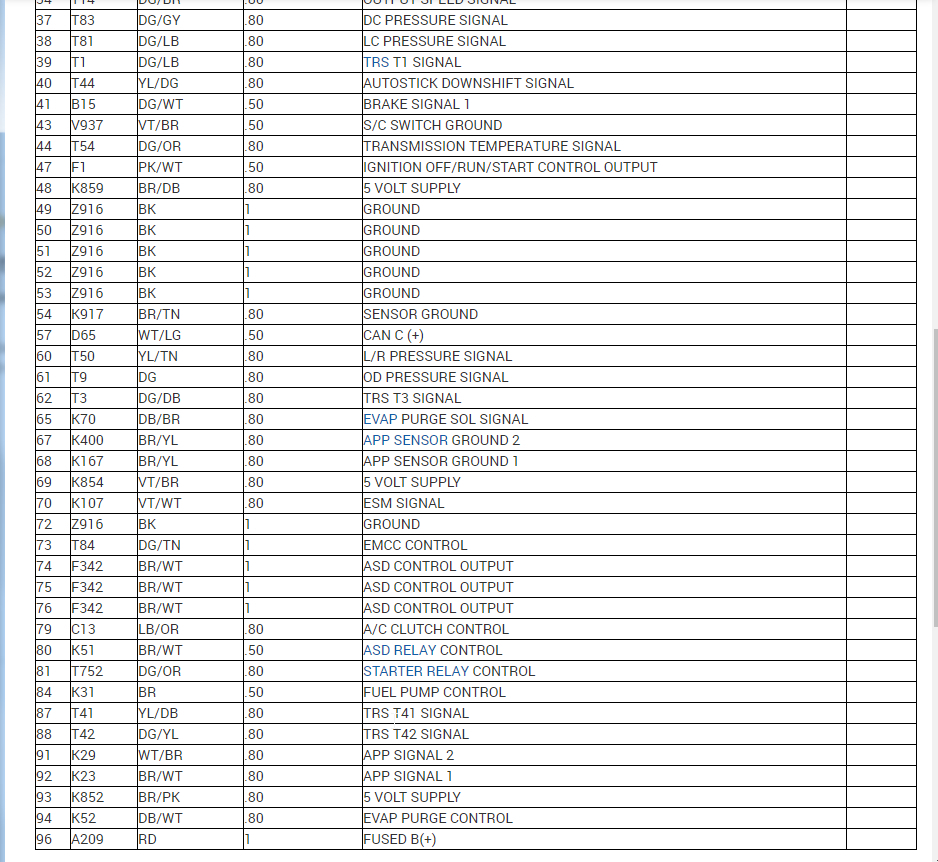
PCM C1 pin 96 12.7Vdc & lights the test light.
I'm finally convinced that this wiring is good.
I found a Remy tech service bulletin on Chrysler charging systems that has more info on these alternators, (at autoprollc. Com website menu under Service Resources under Technical Bulletins). It turns out the sense output (alternator pin 2) is a Kelvin sense circuit that should have no current on it, but it does have a 2.4k Ohms resistor in the alternator to protect it from shorts to ground. That's where the 2.333k Ohms came from, and the voltage drop on alternator pin2 when the engine is started.
I'm not convinced the new PCM is good, but apparently there is a 5V turn on voltage to the EVR circuit when the PCM determines it should be turned on.
I haven't found the inputs the PCM requires to determine that the ignition is on and the engine is running. I haven't heard of any other requirements. Thanks for your help.
Was this
answer
helpful?
Yes
No
Sunday, November 22nd, 2020 AT 10:35 AM
Tiny
ASEMASTER6371
  • MECHANIC
  • 52,797 POSTS
Good morning,

Yes, this sounds like the PCM itself. The fact you got it to work with one of the others tells me that is the use along with all your checks.

https://www.2carpros.com/articles/how-to-check-a-car-alternator

Did you use the exact same number PCM from your original?

Roy

Was this
answer
helpful?
Yes
No
+1
Tuesday, November 24th, 2020 AT 5:26 AM
Tiny
AVIONICS EAGLE
  • MEMBER
  • 12 POSTS
Yes, the Dodge dealer ordered it and programmed it. Sorry, I haven't been able to get back to it. I was wondering if one of the 5V supply voltages on the PCM pinout is required to turn on the EVR circuit? Or if there is some other sense or sensor input the PCM needs to turn on the EVR circuit?
Was this
answer
helpful?
Yes
No
Tuesday, November 24th, 2020 AT 2:49 PM
Tiny
ASEMASTER6371
  • MECHANIC
  • 52,797 POSTS
Did you use a scan tool to monitor the system? You can turn the alternator on and off through the scan tool.

Voltage checks on the lines are not accurate as there is pulse width modulated signals sent from the PCM.

Roy
Was this
answer
helpful?
Yes
No
Tuesday, November 24th, 2020 AT 2:59 PM
Tiny
AVIONICS EAGLE
  • MEMBER
  • 12 POSTS
Oh, I did replace the alternator. Since it still didn't charge, I took it back and got another one. Still not charging the battery. So with the second new alternator I unplugged the small alternator connector and monitored the battery voltage while I jumped 12.4V battery voltage to pin1 on the alternator. The alternator turned on and I disconnected it when battery voltage got to 16V, so the alternator does work if the regulating voltage is applied. The only question is why the PCM isn't putting out the EVR voltage.
Was this
answer
helpful?
Yes
No
Tuesday, November 24th, 2020 AT 3:09 PM
Tiny
AVIONICS EAGLE
  • MEMBER
  • 12 POSTS
No, I haven't gotten a scan tool yet. Looks like a necessity these days.
Was this
answer
helpful?
Yes
No
Tuesday, November 24th, 2020 AT 3:13 PM
Tiny
ASEMASTER6371
  • MECHANIC
  • 52,797 POSTS
That is controlled by a load detector inside the ECM.

That is why you need a scan tool to monitor what the ECM is commanding.

Roy
Was this
answer
helpful?
Yes
No
+1
Tuesday, November 24th, 2020 AT 3:19 PM

Please login or register to post a reply.

Sponsored links