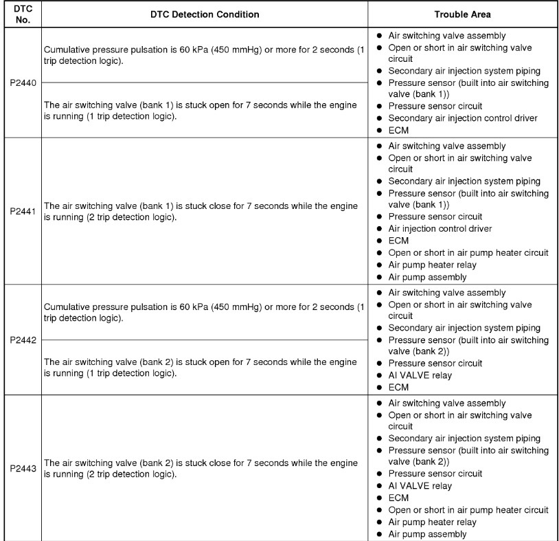
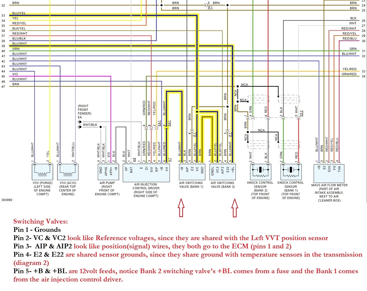
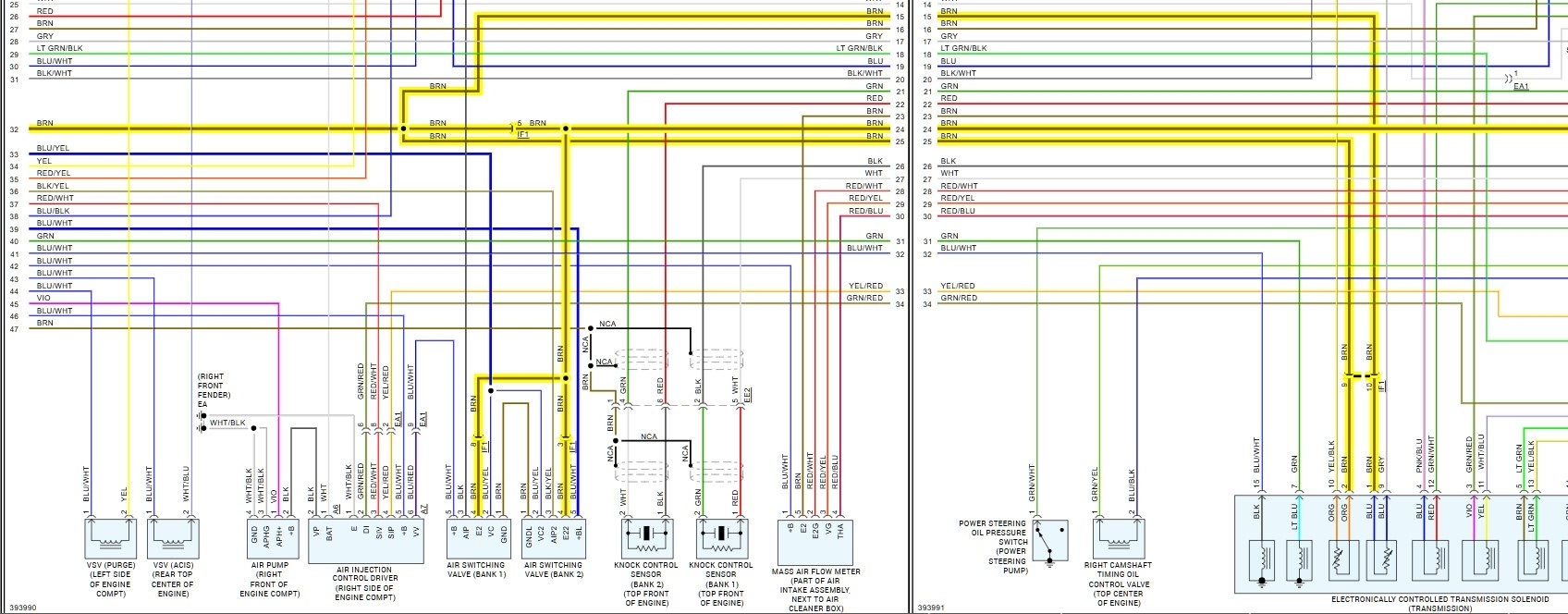
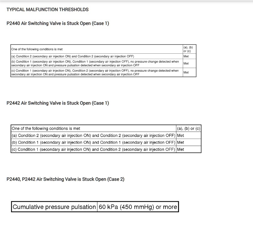
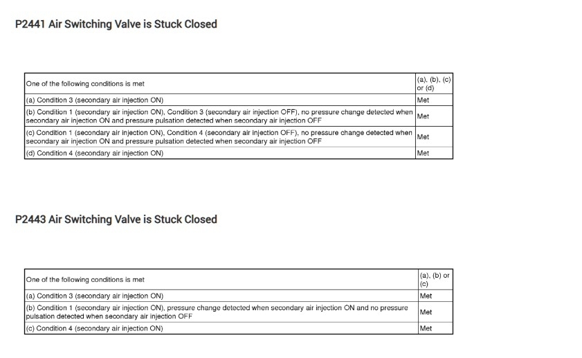
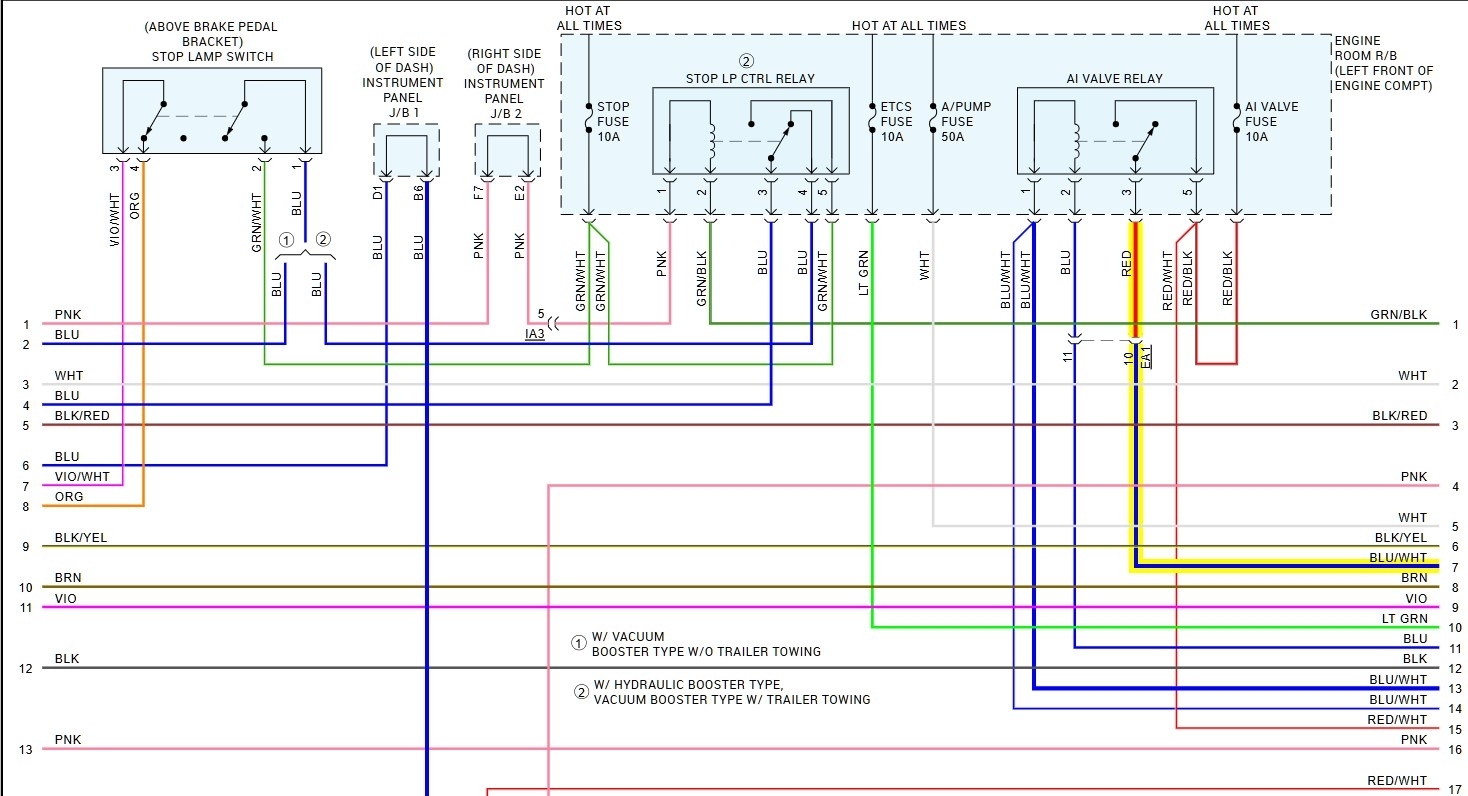
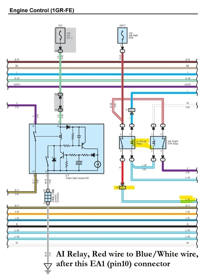
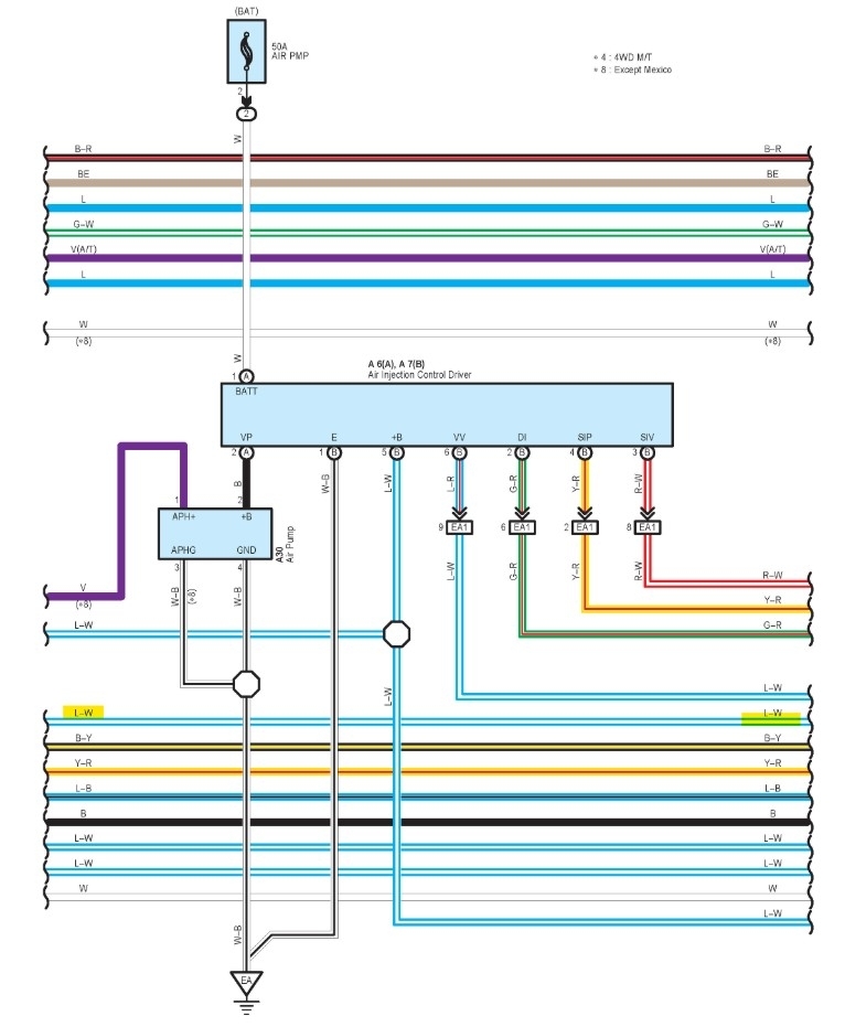
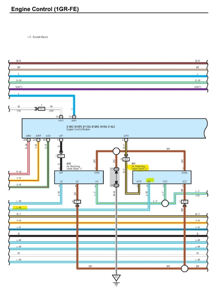
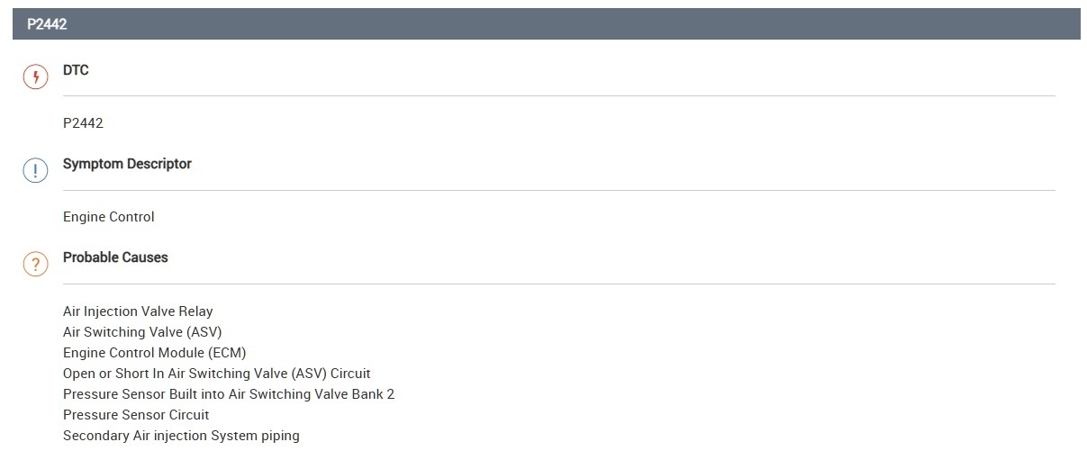
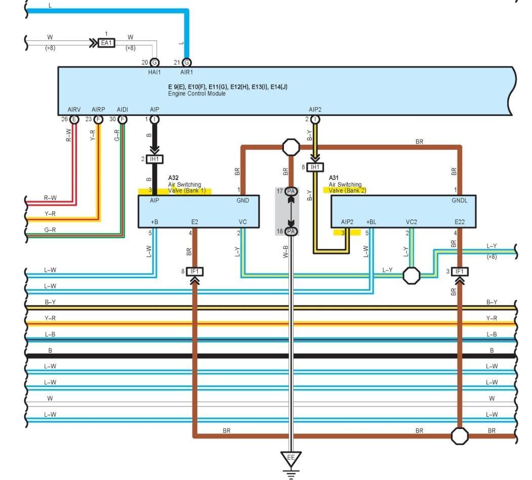
Hello, so obviously there's two switching valves one for each bank and an air pump, I'll put up the wiring diagrams for them both, each has a pressure switch in them for the control module to detect changes when opening or closing each valve, from the diagrams I'm seeing , each switching valve has a B+ and they share a ground, it looks like the bank switching valve gets power from the control module, whereas bank 2 valve might have its own B+, so those are things to check first, since you're getting a stuck closed code and a stuck open code, which take a number of seconds to set, the valve might be not reacting in time before setting codes or its intermittently sticking.
It also looks like each switching valve has a reference voltage for the pressure sensors which would be logical, a Ref voltage, Signal, and Ground for 3 wire sensors, or 2 wire pressure sensors use a Ref voltage as well, somewhere between 5v and 12v. You will see which wires are B+ and ground, etc., on the diagrams.
Load testing the B+ and Grounds would be the best place to start, using a higher amperage test light, such as a head lamp bulb, turn signal bulb, something that will pull a few amps. Let me get diagrams together for you but check each switching valves connectors for any possible oil or water intrusion, I find oil in these when the valve cover leaks, oil also effects the rubber hoses going to the air pump or valves when that happens as well.
May 1, 2025 at 10:57 AM