Code P1491?

Tiny
2000 DODGE DAKOTA
  • MEMBER
  • 2000 DODGE DAKOTA
  • 3.9L
  • V6
  • 2WD
  • AUTOMATIC
  • 110,000 MILES
For the last 5 years I have been experiencing issues with the P1491 code. The Rad Fan Relay melts (see photos) and after replacing the relay I am only able to clear the code by replacing the PCM.

This is temporary solution was recommended by a local mechanic. (Replacing the PCM (Powertrain Control Module) and replacing the Rad Fan Relay.)

Unfortunately, I have now replaced the relay and PCM 4 times and this solution is getting expense. I would greatly appreciate assistance in correcting the code P1491 so that I do not have to replace the PCM and relay every year.

Thank you.

Wednesday, December 28th, 2022 AT 12:59 PM

7 Replies

Tiny
JACOBANDNICKOLAS
  • MECHANIC
  • 108,133 POSTS
Hi,

I'm not sure why replacing the PCM is being suggested. That only actuates the relay when it's needed. Actually, the PCM provides a ground path to actuate the relay. Don't waste your money. That isn't causing the issue unless the fan runs at all times.

Have you ever replaced the fan motor? It may be drawing too much amperage. Also, I want you to check something for me. I want to know what the alternator output is with the engine running. All you need is a voltmeter or multimeter.

Here is a link that explains how it's done:

https://www.2carpros.com/articles/how-to-check-a-car-alternator

Next, I need you to check the pins in the relay box to make sure there is no evidence of a weak connection. When electric arcs or has to jump, it creates heat. Also, check the connector at the blower motor as well for evidence of it overheating.

One last check, the fuse that is to power the fan motor is to be a 30-amp fuse. It is fuse 2 in the power distribution box under the hood. Make sure a heavier gauge fuse wasn't used.

I attached the wiring schematic related to the radiator cooling fan which is very basic. If I had to guess, either we have a weak connection causing heat to build or the fan motor is drawing too much power.

Let me know what you find.

Joe

See pic below.
Was this
answer
helpful?
Yes
No
+1
Wednesday, December 28th, 2022 AT 10:15 PM
Tiny
2000 DODGE DAKOTA
  • MEMBER
  • 5 POSTS
Hi Joe,

Thank you for the post. I should have mentioned that previously the fan would be stuck on and could only reset the code and shut off the fan by replaying the relay and replacing the PCM. I replaced the fan last year just to see if that would make a difference. This time the fan is not stuck on so I am hopeful this code can be repaired with purchasing another PCM. The alternator is reading 14.1v. When I checked the wiring, I could not locate a short. A 30-amp fuse is in position 2. Any other thoughts would be appreciated.

Thank you.
Was this
answer
helpful?
Yes
No
Sunday, January 1st, 2023 AT 5:46 PM
Tiny
JACOBANDNICKOLAS
  • MECHANIC
  • 108,133 POSTS
Hi,

The only thing I can think of that would cause that much heat is either the motor pulling too many amps or a loose/poor connection.

Check to make sure where the relay connects there isn't corrosion, or a pin being pushed in. And making a weak connection. Check at the fan as well.

When electric arcs, it creates a lot of heat. It's just a theory at this point, but one that is worth checking.

Let me know.

Joe
Was this
answer
helpful?
Yes
No
Monday, January 2nd, 2023 AT 3:43 PM
Tiny
2000 DODGE DAKOTA
  • MEMBER
  • 5 POSTS
I'm still trying to locate the issue. I would like to try rewriting the radiator fan relay. Do you believe this might help? If so why type of wire should I use?
Was this
answer
helpful?
Yes
No
Monday, February 6th, 2023 AT 9:12 AM
Tiny
CARADIODOC
  • MECHANIC
  • 33,729 POSTS
Hi guys. I've been waiting to learn the solution, but in the meantime, please allow me to add a few comments. Rewiring what the engineers designed is not the answer. If that were the case, every truck would have this problem and there would have been a recall to address it.

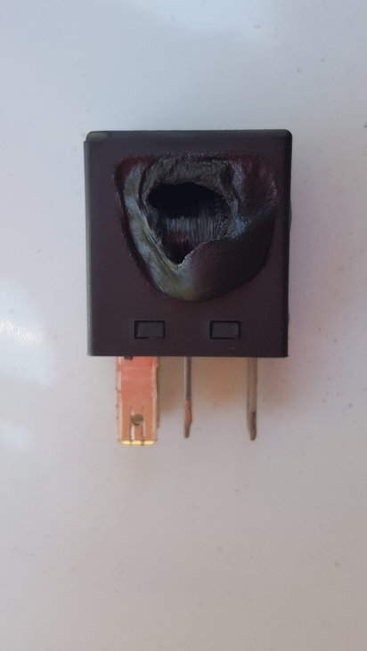
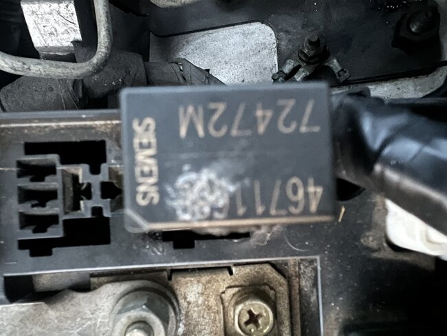
I think Joe had the answer in the first reply, about the fan motor drawing too much current. It's not uncommon to see overheated terminals in high-current circuits like ignition switches, heater fan switches, and relay sockets. There's multiple causes, but in this case, with a badly overheated relay, it's more likely due to excessive arcing across the contacts. That arcing occurs when very high current is switched off.

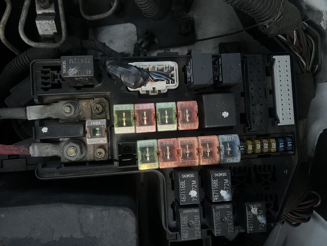
The other thing to look for, especially when someone complains of multiple repeat failures, is the heat from poor relay contacts or poor switch contacts will migrate out and degrade the connector terminals, usually to the point it melts the surrounding plastic connector body. Likewise, that bad connection can occur between a pair of mating connector terminals, then the heat generated can migrate into the switch or relay causing those contacts to overheat and start a new failure. Both the switch or relay, and the mating terminals must be replaced at the same time, otherwise the problem will continue to recur.

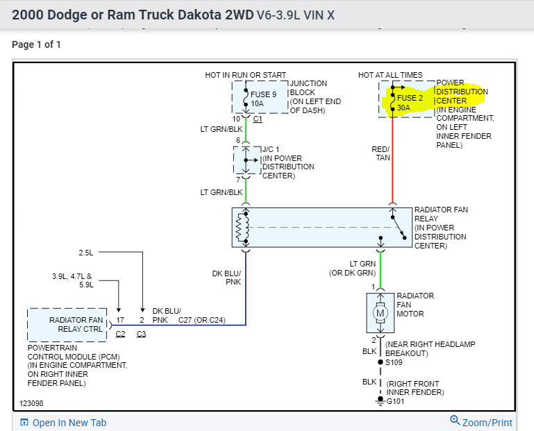
I have a suspicion the original failure was caused by a tight radiator fan motor. Without going into unnecessary detail, the more a motor is loaded down, the more current it will draw. Radiator fan motors typically draw around 15 amps. That's more than the typical switching transistors inside computers like to handle, so they use a relay instead. The Engine Computer is only supplying a tiny fraction of an amp to turn on the relay. After that, it has no idea how much current that relay is passing. That's why Joe also couldn't understand the need to replace the computer. Given the really excessive heat generated inside the relay, it's almost certain the contacts arced so many times, they welded themselves together. It's the stuck relay that kept the fan running, not the computer keeping the relay turned on. Terminals arced together like that do not create a nice solid connection, so more heat is generated, as happened here.

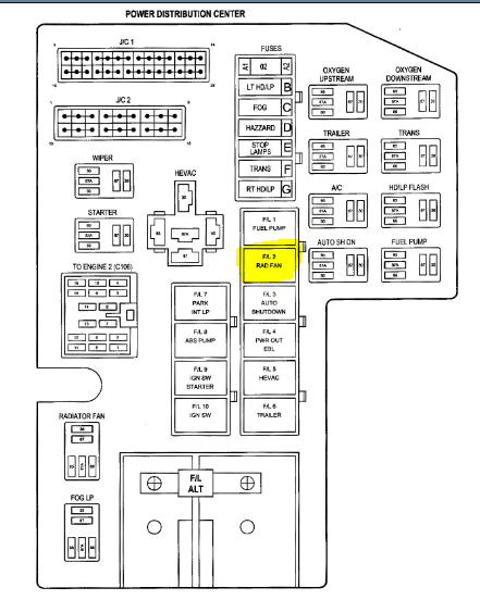
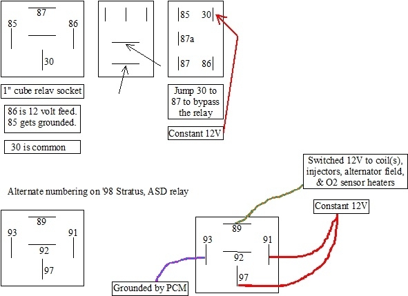
I see you did replace the fan motor already. Was that a new one or a used one from a salvage yard? If it was a used one, it might also have tight bearings, but more than likely, the cause of the repeat failures was never addressed, that being the terminals in the relay socket. As badly as that first relay was overheated, it's a good bet the terminals in the socket are blackened or discolored. If you see that, I would address that the same way I do ignition switch connectors. You only need to look at the two terminals for the high-current switched side of the relay. Those will be the two fatter wires in the socket. I also put this drawing together to show them.

You can harvest a pair of terminals with a few inches of wire at a salvage yard, or, I use a new pair of universal spade terminals. Those work better for ignition switches. The job will be easier for you if you can get the old terminals out and the new ones to plug in solidly. If not, when the plastic is badly melted, cut all of it away around those two terminals. When the terminals got hot enough to discolor, the wires are going to be hardened for about the first four inches. Solder won't adhere to that, so cut those first few inches away too. This is why you want to get a good four to five inches of wire with terminals you get from a salvage yard.

With new terminals, splice in the four inches of new wire of the same gauge, solder the splices, then seal them with heat-shrink tubing. Never use electrical tape in a vehicle as it will unravel into a gooey mess on a hot day. Crimp the universal spade terminals to the new wires, but solder them too for the best connection. If the relay box is still okay, plug those original-style terminals into the socket and the repair is done. If the plastic had to be cut away, and / or you're using universal replacement terminals, those will have to be plugged into the relay individually. Consider squeezing them first so they make a really solid contact. For a relay, you might need to make that six or seven inches of new wire so they can be pushed up through the socket. That leaves you something to grab onto when plugging them in separately. Then push the relay into the socket so the other two terminals can plug in.

That gets the circuit working, but I wouldn't consider the repair completed yet. To ensure it's working properly, make the computer operate the relay to verify the fan runs. You can wait and wait and wait for the idling engine to heat up, or use a scanner to command the radiator fan relay on, or a simple trick is to unplug the coolant temperature sensor. It will have two wires in its connector, and will be on or near the thermostat housing at the end of the upper radiator hose. Unplugging it causes the computer to turn on the fan relay because it won't know engine temperature. It does that in case it's getting too hot. This will set a diagnostic fault code and turn on the Check Engine light, but that code will self erase after 50 engine restarts. The relay will turn off a few seconds after the coolant temperature sensor is reconnected, and the Check Engine light should be off the next time the engine is restarted. On a few models it turns off right away while the engine is running. By the way, when unplugging the sensor, the engine doesn't have to be running. You just need to have the ignition switch in "run".

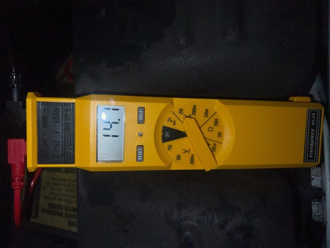
For the last step, when the relay switches off, watch how long the fan takes to coast to a stop. If it stops instantly or within a couple of seconds, it has tight bearings and the same problem is going to occur. The fan should coast for a good three to five seconds. Finally, I would really want to know how much current the fan motor is drawing. You'll need an amp meter that can measure at least up to 20 amps. If you have an older direct meter that gets inserted in series into one of the motor's wires, you can do that right at one of the new terminals you just installed, before you plug it into the relay. There will be some minor sparking at the last probe to be connected, then the motor will start running. It occurs too quickly to see, but it takes about 20 to 25 amps to get the motor started, then it will drop down to the reading we want to see within a fraction of a second. If you find it's around 15 amps or less, I'd consider the job done.

This type of amp meter can be inserted anywhere in either wire, including right at the motor's connector, but it's hard to find amp meters today that can read that high. Most amp meter functions on today's multimeters can only read to five or ten amps. Trying to read higher values can damage the meter or blow its internal fuse. The best alternative is to use a meter with an inductive pickup. Those clamp around a wire just like we used to do with timing lights on spark plug wires. You may need to visit a mechanic for this. They have professional charging system load testers that use an inductive pickup. Those are accurate enough for this circuit. If you have access to such a tester, remember it must be clamped around just one wire. There's at least two wires at the motor. If you clamp around both of them, the current going one way through one wire will be offset by the current going the other way through the other wire. Current has to be the same value in both wires, so the tester will see the sum of the two, or 0 amps.

Hope that helps. I'll be waiting to learn the final solution.
Was this
answer
helpful?
Yes
No
Monday, February 6th, 2023 AT 3:11 PM
Tiny
2000 DODGE DAKOTA
  • MEMBER
  • 5 POSTS
Thank you for the in-depth reply. It is going to take me awhile to work through those instructions.

Too bad I cannot have you work on my truck. Sounds like you know a lot about this issue.
Was this
answer
helpful?
Yes
No
Thursday, February 9th, 2023 AT 1:41 PM
Tiny
CARADIODOC
  • MECHANIC
  • 33,729 POSTS
Joe will get you there too. This happens to be an area I was involved with multiple times at the dealership, including once on a K-car being repaired by a very experienced transmission specialist. He found and replaced the tight radiator fan motor, but got confused when the new one wouldn't run, even though he found 12 volts at its connector.

I suggested he measure the voltage with a cheap test light instead of his expensive voltmeter. He had 0 volts with the test light. Turned out that circuit was protected by a "fuse link wire", which was real common back then. A bundle of them run around the left strut tower. When they burn open, as this one had, it leaves a carbon track behind inside the insulation where the arcing occurs as the wire melts. That carbon, similar to what used to commonly happen in distributor caps, passed enough current for the voltmeter to incorrectly see it and show 12 volts, but not enough current could get through to run the test light. That's why I always ask people to make voltage checks in these types of circuits with a test light.

I have to repeat too, the Engine Computer just uses a small fraction of an amp to turn on a relay. In this circuit, it has no idea what the relay does after that, so if it's passing excessive current, that has to do only with that high-current side of the relay which includes its contacts, the fan motor, and the fuse.

The difference is in the K-car story, the fuse link wire was the weak link in the chain, as it was designed to be, so that is what failed. As the fan motor became loaded down more and more as the bearings became tight, it drew higher and higher current until the fuse link gave way. Something different is happening in your truck. The pitted or arced relay contacts developed a little resistance, which we do not want. Current flowing through any resistance develops heat. That heat usually causes more resistance to develop which results in even more heat. If that gets bad enough, you get the results you see with your melted relay. Also, more resistance in the circuit causes a drop in current flow, so in your case, there's less current flowing through the fuse device, not more as happened in the K-car. Your fan motor will run slower, and that makes it try to draw higher current which aggravates the problem. For anyone who understands basic electrical theory, what I just said would seem wrong, or counter-intuitive. That's an explanation for another day.

Blackened or discolored relay or switch terminals also introduce resistance in the circuit, and again, current flowing through them creates heat. We don't see melted plastic relay connectors real often, but that is common on ignition switches and heater fan switches. There's usually three or four separate switches built into an ignition switch. The part that overheats is always the part that switches the accessory circuits on and off, which includes the heater fan. This happens most often to drivers who are in the habit of turning the ignition switch on and off while the heater fan is set to one of its higher speeds. That forces the ignition switch to turn that high current on and off, and that greatly increases the amount of arcing that takes place across those contacts. That's where the overheating contacts starts, and once that first little resistance occurs, the problem will keep getting worse until the connector body holding the terminals melts.

I apologize for sticking my nose into your conversation. I just can't stay quiet when I have so much wonderful experience that just has to be shared. I'll still be waiting to learn the final solution.
Was this
answer
helpful?
Yes
No
Thursday, February 9th, 2023 AT 3:30 PM

Please login or register to post a reply.

Sponsored links