Hi and thanks for using 2CarPros.com.
The price will be based on which O2 sensor needs replaced. This is an easy job, and you may want to consider doing it yourself.
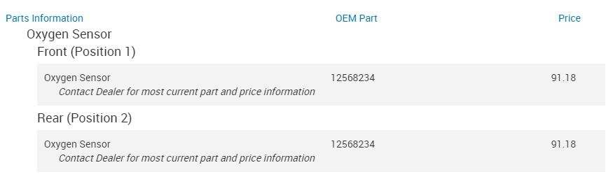
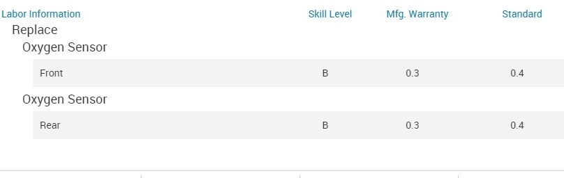
I attached two pictures. The first lists original equipment parts for both sensors. You can get aftermarket ones for less. The second picture is the time in labor to replace them. You will need to multiply the listed amount times the hourly rate of the mechanic doing the work. Please note that both take less than an hour. Therefore, when determining labor, take the hourly labor rate x .4. Example. 100.00 an hour X .4 = 40.00
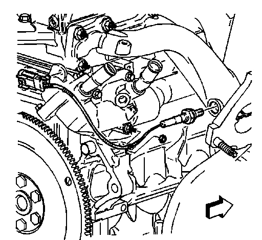
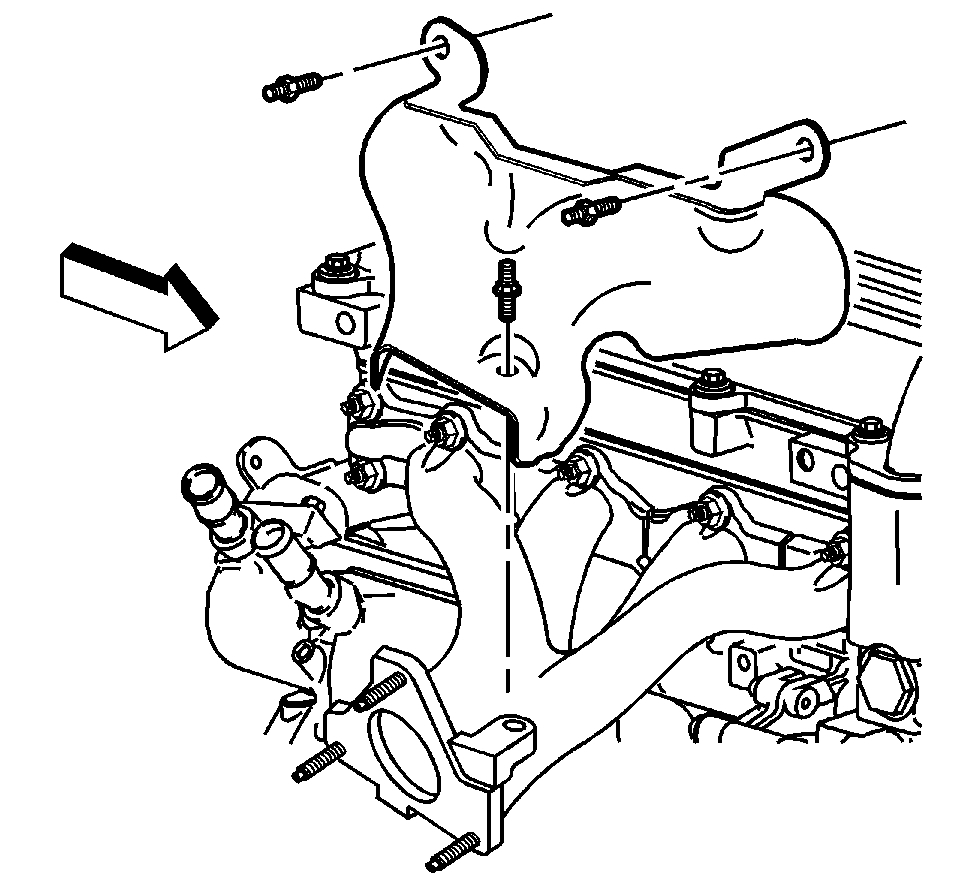
Let me know if this helps. If you decide to replace it yourself, here are the directions for both. I will start with position 1 (front) Pictures 3 through 6 correlate with these directions.
__________________
HEATED OXYGEN SENSOR REPLACEMENT - POSITION 1
TOOLS REQUIRED
J 39194-C Oxygen Sensor Wrench
REMOVAL PROCEDURE
NOTE:
- The oxygen sensor uses a permanently attached pigtail and connector. Do not remove the pigtail from the oxygen sensor. Damage to or removal of the pigtail connector could affect proper operation of the oxygen sensor.
- The use of excessive force may damage the threads in the exhaust manifold/pipe.
IMPORTANT:
- The in-line connector and louvered end must be kept clear of grease, dirt or other contaminants. Avoid using cleaning solvents of any type. DO NOT drop or roughly handle the oxygen sensor.
- The oxygen sensor may be difficult to remove when the engine temperature is less than 48°C (120°F).
1. Remove the exhaust manifold heat shield.
2. Disconnect the oxygen sensor harness connector.
3. Remove the oxygen sensor using J 39194-C.
INSTALLATION PROCEDURE
1. Coat the threads of the oxygen sensor with anti-seize compound GM P/N 12377953, or equivalent, if necessary.
IMPORTANT: A special anti-seize compound is used on the oxygen sensor threads. The compound consists of a liquid graphite and glass beads. The graphite will burn away, but the glass beads will remain, making the sensor easier to remove. New or service sensors will have the compound applied to the threads. If a sensor is removed and is to be reinstalled, the threads must have an anti-seize compound applied before installation.
2. Install the oxygen sensor.
NOTE: Refer to Fastener Notice.
Tighten the oxygen sensor to 30 N.m (22 lb ft).
3. Connect the oxygen sensor harness connector.
4. Install the exhaust manifold heat shield.
_______________________________________________
Position 2 (rear) Pictures 7 through 10 correlate with these directions.
EATED OXYGEN SENSOR REPLACEMENT - POSITION 2
TOOLS REQUIRED
J 39194-C Oxygen Sensor Wrench
REMOVAL PROCEDURE
1. Raise and support the vehicle. Refer to Vehicle Lifting.
2. Remove the wheel drive shaft heat shield.
3. Note the routing of the heated oxygen sensor (HO2S) electrical harness.
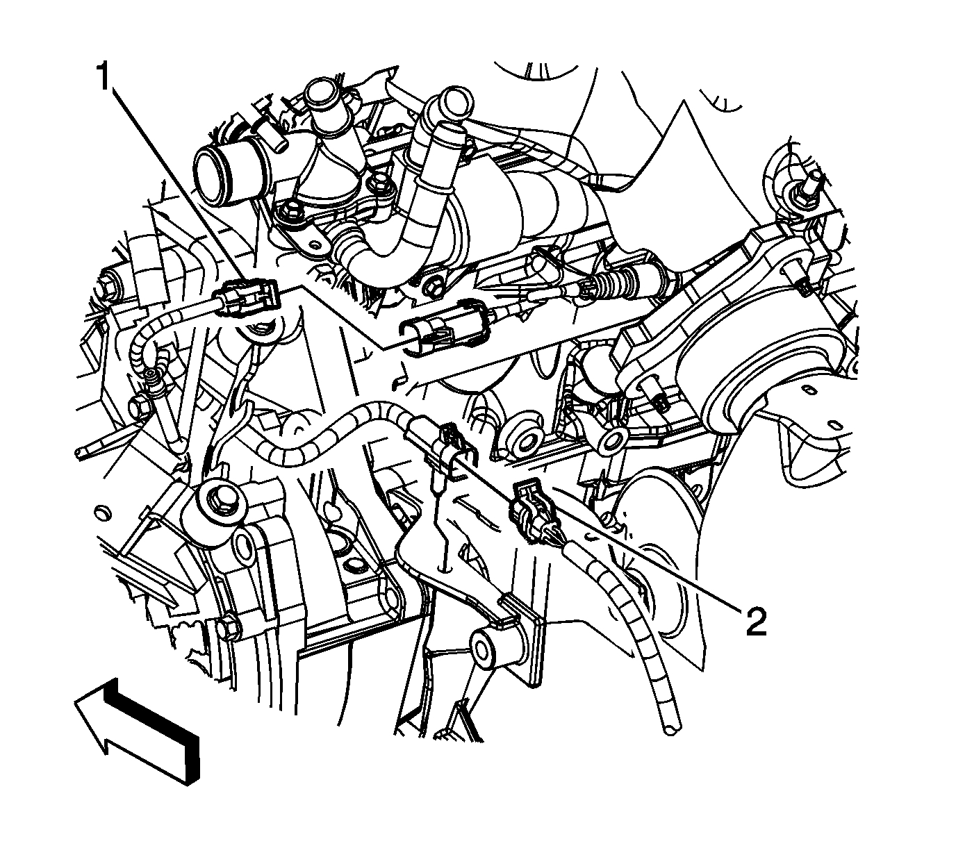
4. Disconnect the HO2S electrical connector (2), in the engine compartment.
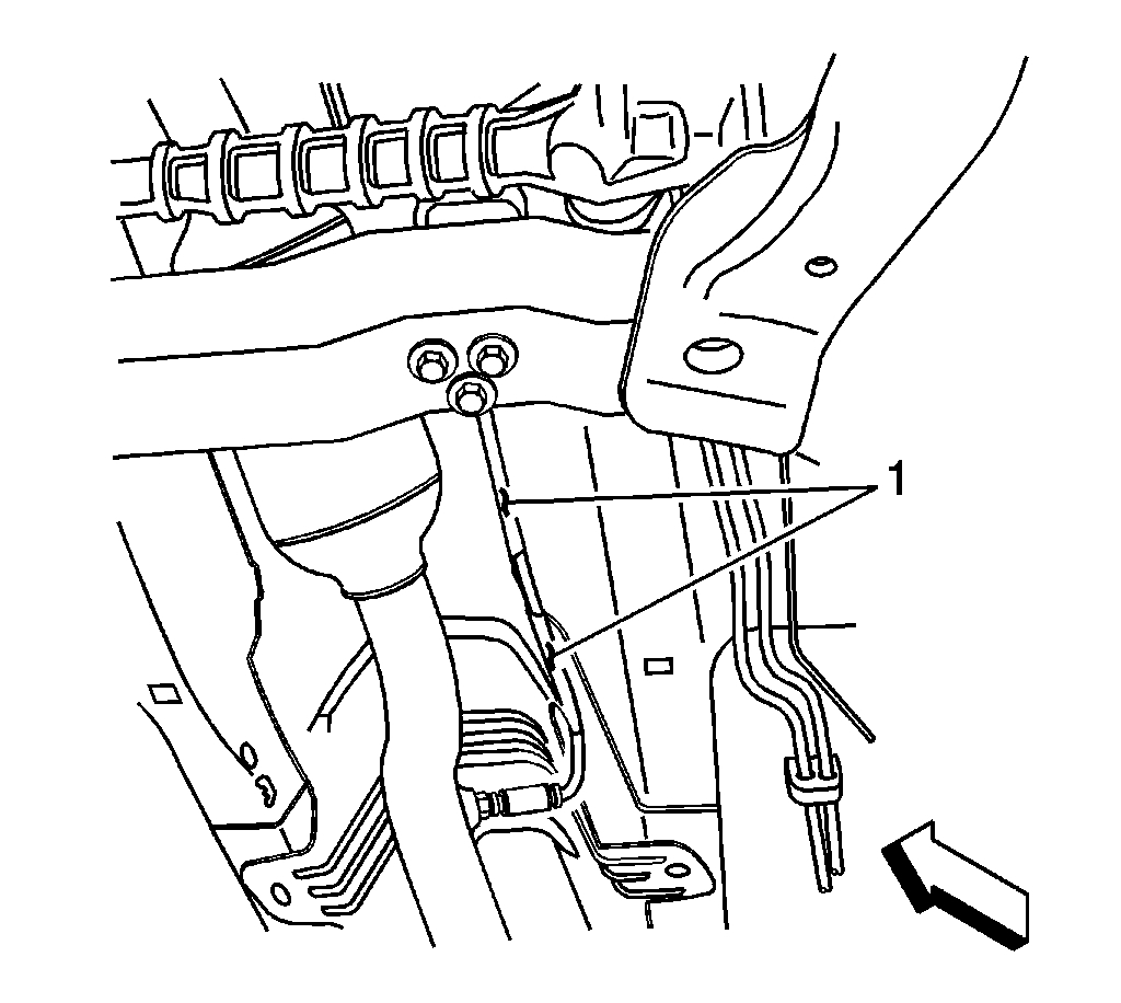
5. Carefully bend the edge of the channel on the LH side of the exhaust heat shield outboard, just enough to release the HO2S electrical harness (1).
6. Using the J 39194 carefully remove the HO2S.
NOTE:
- Refer to Heated Oxygen and Oxygen Sensor Notice.
- Refer to Excessive Force and Oxygen Sensor Notice.
7. Lower the HO2S electrical harness away from the underbody.
INSTALLATION PROCEDURE
IMPORTANT: A special anti-seize compound is used on the HO2S threads. The compound consists of a liquid graphite and glass beads. The graphite will burn away but the glass beads will remain, making the sensor easier to remove. New or service sensors already have the compound applied to the threads. If the sensor is removed and is to be reinstalled, the threads must be coated with an anti-seize compound before reinstallation.
1. If reinstalling the old HO2S, coat the threads with anti-seize compound, GM P/N 12377953, or equivalent.
2. Carefully install the HO2S to the pipe.
3. Using the J 39194, or equivalent, tighten the HO2S.
NOTE: Refer to Component Fastener Tightening Notice.
Tighten the HO2S to 41 N.m (30 lb ft).
4. Install the HO2S electrical harness into position as noted before removal.
5. Carefully bend the edge of the channel (1) on the LH side of the exhaust heat shield inboard, just enough to secure the HO2S electrical harness in the channel.
IMPORTANT: Use care when securing the HO2S electrical harness into the channel on the exhaust heat shield, to not pinch the wires.
6. Connect the HO2S electrical connector (2).
7. Install the wheel drive shaft heat shield.
8. Lower the vehicle.
____________________________________________
Let me know if this helps or if you have other questions.
Take care,
Joe
Images (Click to enlarge)
Oct 10, 2018 at 7:17 PM