Hi,
It sounds like the pump itself may be going bad or just may be louder than your old one. However, it is louder than one would expect. Is there any warranty on the work that was done? Other than the noise, are the brakes working properly?
________________________________
I don't know if replacing it is something you would like to do, but here are the directions for removal and replacement. Note that even a new pump may be louder than the original one.
________________________________
Removal
2012 Toyota Camry L4-2.5L (2AR-FXE) Hybrid
Removal
Vehicle Brakes and Traction Control Power Brake Assist Hydraulic Brake Booster Pump Service and Repair Removal and Replacement Removal
REMOVAL
BRAKE SYSTEM (OTHER): BRAKE BOOSTER PUMP: REMOVAL
1. PRECAUTION
NOTICE:
After turning the power switch off, waiting time may be required before disconnecting the cable from the negative (-) auxiliary battery terminal. Therefore, make sure to read the disconnecting the cable from the negative (-) auxiliary battery terminal notices before proceeding with work See: Vehicle > Technician Safety Information > Repair Instruction - Precaution.
2. RECOVER REFRIGERANT FROM AIR CONDITIONING SYSTEM See: Heating and Air Conditioning > Removal and Replacement > Refrigerant
3. DISABLE BRAKE CONTROL See: Vacuum Brake Booster > Removal and Replacement > Removal
4. REMOVE WINDSHIELD WIPER MOTOR AND LINK ASSEMBLY
See: Wiper Motor > Removal and Replacement > Removal
5. REMOVE FRONT OUTER COWL TOP PANEL SUB-ASSEMBLY See: Vacuum Brake Booster > Removal and Replacement > Removal
6. REMOVE COOL AIR INTAKE DUCT SEAL See: Grille > Removal and Replacement > Removal
7. REMOVE INLET AIR CLEANER ASSEMBLY See: Engine > Removal and Replacement > Removal
8. REMOVE AIR CLEANER CAP SUB-ASSEMBLY See: Throttle Body > Removal and Replacement > Removal
9. REMOVE AIR CLEANER FILTER ELEMENT SUB-ASSEMBLY
10. REMOVE AIR CLEANER CASE SUB-ASSEMBLY See: Engine > Removal and Replacement > Removal
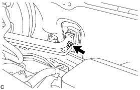
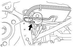
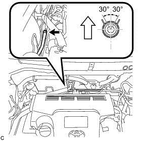
11. SEPARATE AIR CONDITIONER TUBE AND ACCESSORY ASSEMBLY
(a)Remove the bolt from the hook connector.
pic 1
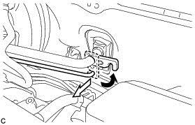
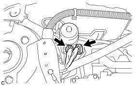
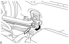
(b)Turn the hook connector and separate the air conditioning tube and accessory assembly from the air conditioning unit.
pic 2
NOTICE:
* Do not deform the piping.
* Do not damage the plastic clamp.
(c)Remove the O-ring from the air conditioning tube and accessory assembly.
NOTICE:
Seal the openings of the disconnected parts using vinyl tape to prevent entry of moisture and foreign matter.
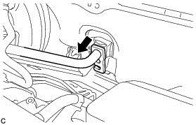
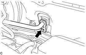
12. SEPARATE SUCTION HOSE SUB-ASSEMBLY
(a)Separate the suction hose sub-assembly from the air conditioning unit.
pic 3
NOTICE:
* Do not deform the piping.
* Do not damage the plastic clamp.
(b)Remove the O-ring from the suction hose sub-assembly.
NOTICE:
Seal the openings of the disconnected parts using vinyl tape to prevent entry of moisture and foreign matter.
13. DRAIN BRAKE FLUID
NOTICE:
If brake fluid leaks onto any painted surface, immediately clean it off.
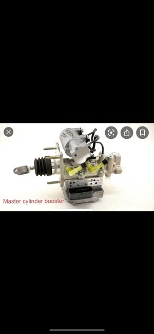
14. SEPARATE BRAKE MASTER CYLINDER RESERVOIR ASSEMBLY See: Vacuum Brake Booster > Removal and Replacement > Removal
15. SEPARATE NO. 1 BRAKE ACTUATOR TUBE See: Vacuum Brake Booster > Removal and Replacement > Removal
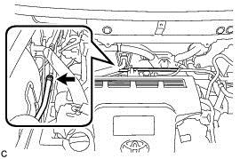
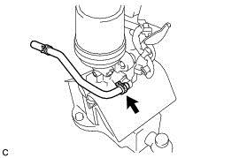
16. DISCONNECT NO. 1 BRAKE ACTUATOR HOSE
(a)Move the clip and disconnect the No. 1 brake actuator hose from the No. 1 brake actuator tube.
pic 4
17. DISCONNECT FRONT NO. 1 BRAKE TUBE
(a)Using a union nut wrench, disconnect the front No. 1 brake tube from the brake booster pump assembly.
pic 5
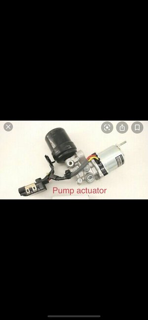
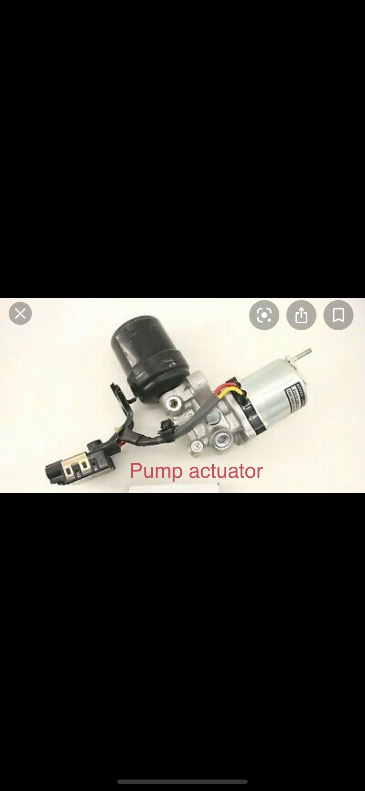
18. REMOVE BRAKE BOOSTER PUMP ASSEMBLY WITH BRACKET
(a)Disconnect the 2 connectors from the brake booster pump assembly.
pic 6
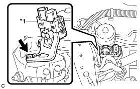
(b)Remove the bolt and separate the connector box of the brake booster pump assembly from the brake actuator bracket assembly.
pic 7
Text in Illustration
pic 8
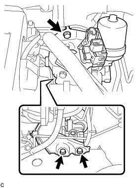
(c)Remove the 3 bolts and brake booster pump assembly with bracket from the vehicle body.
pic 9
NOTICE:
Do not kink or damage the brake line, suction hose sub-assembly or air conditioning tube and accessory assembly.
19. REMOVE NO. 1 BRAKE ACTUATOR HOSE
(a)Move the clip and remove the No. 1 brake actuator hose from the brake booster pump assembly.
pic 10
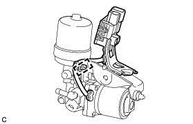
20. REMOVE BRAKE BOOSTER PUMP ASSEMBLY
(a)Disengage the wire harness clamp from the brake actuator bracket assembly.
pic 11
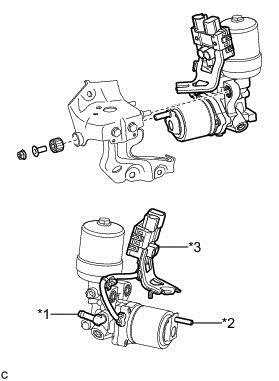
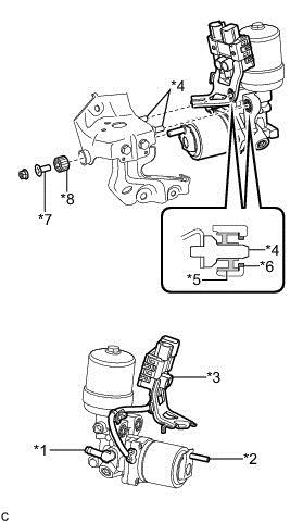
(b)Remove the nut, brake actuator case collar, brake booster pump bushing and brake booster pump assembly from the brake actuator bracket assembly.
pic 12
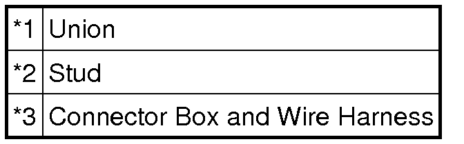
Text in Illustration
pic 13
NOTICE:
* Do not carry the brake booster pump assembly by the parts shown in bold (*1, *2 and *3) in the illustration.
* Do not drop the brake booster pump assembly when carrying it.
* Be careful not to allow any brake fluid to enter the connector.
______________________________
Install
2012 Toyota Camry L4-2.5L (2AR-FXE) Hybrid
Installation
Vehicle Brakes and Traction Control Power Brake Assist Hydraulic Brake Booster Pump Service and Repair Removal and Replacement Installation
INSTALLATION
BRAKE SYSTEM (OTHER): BRAKE BOOSTER PUMP: INSTALLATION
1. INSTALL BRAKE BOOSTER PUMP ASSEMBLY
(a)Insert the stud of the brake booster pump assembly to the hole of the brake actuator bracket assembly, and insert the 2 pins of the brake actuator bracket assembly to the 2 brake booster pump bushings (*5).
pic 14
Text in Illustration
pic 15
NOTICE:
* Do not carry the brake booster pump assembly by the parts shown in bold (*1, *2 and *3) in the illustration.
* Do not drop the brake booster pump assembly when carrying it.
* Be careful not to allow any brake fluid to enter the connector.
* When installing the brake booster pump assembly to the brake actuator bracket assembly, confirm that the 2 brake booster pump collars (*6) and 2 brake booster pump bushings (*5) are installed on the brake booster pump assembly.
* Do not remove the hole plugs before installing a new brake booster pump assembly because the brake booster pump assembly is filled with brake fluid.
(b)Install the brake actuator case collar (*7), brake booster pump bushing (*8) and brake booster pump assembly to the brake actuator bracket assembly with the nut.
Torque : 5.4 Nm (55 kgf-cm, 48 in-lbf)
(c)Engage the wire harness clamp to the brake actuator bracket assembly.
2. INSTALL NO. 1 BRAKE ACTUATOR HOSE
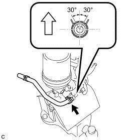
(a)Install the No. 1 brake actuator hose to the brake booster pump assembly with the clip.
pic 16
Text in Illustration
pic 17
NOTICE:
* Match the identification mark of the No. 1 brake actuator hose and the rib of the brake booster pump assembly.
* Install the clip within the range shown in the illustration.
3. INSTALL BRAKE BOOSTER PUMP ASSEMBLY WITH BRACKET
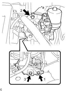
(a)Engage the claw to set the brake booster pump assembly with bracket to the vehicle body.
pic 18
Text in Illustration
pic 19
NOTICE:
Do not kink or damage the brake line, suction hose sub-assembly or air conditioning tube and accessory assembly.
(b)Install the 3 bolts to secure the brake booster pump assembly with bracket to the vehicle body.
Torque : 19 Nm (194 kgf-cm, 14 ft-lbf)
NOTICE:
Tighten the 3 bolts in the order shown in the illustration.
(c)Engage the claw to set the connector box to the brake actuator bracket assembly.
pic 20
Text in Illustration
pic 21
(d)Install the bolt to secure the connector box to the brake actuator bracket assembly.
Torque : 8.0 Nm (82 kgf-cm, 71 in-lbf)
(e)Connect the 2 connectors to the brake booster pump assembly.
4. CONNECT FRONT NO. 1 BRAKE TUBE
(a)Using a union nut wrench, connect the front No. 1 brake tube to the brake booster pump assembly.
Torque : 15 Nm (155 kgf-cm, 11 ft-lbf)
NOTICE:
Use the formula to calculate special torque values for situations where the union nut wrench is combined with a torque wrench See: Vehicle > Technician Safety Information > Repair Instruction - Precaution.
5. CONNECT NO. 1 BRAKE ACTUATOR HOSE
(a)Connect the No. 1 brake actuator hose to the No. 1 brake actuator tube with the clip.
pic 22
Text in Illustration
pic 23
NOTICE:
* Match the identification mark of the No. 1 brake actuator hose and No. 1 brake actuator tube.
* Install the clip within the range shown in the illustration.
6. BLEED NO. 1 BRAKE ACTUATOR TUBE See: Vacuum Brake Booster > Removal and Replacement > Installation
7. INSTALL NO. 1 BRAKE ACTUATOR TUBE See: Vacuum Brake Booster > Removal and Replacement > Installation
8. INSTALL BRAKE MASTER CYLINDER RESERVOIR ASSEMBLY See: Vacuum Brake Booster > Removal and Replacement > Installation
9. INSTALL SUCTION HOSE SUB-ASSEMBLY
(a)Remove the vinyl tape from the openings of the disconnected parts.
(b)Sufficiently apply compressor oil to a new O-ring, the fitting surface of the suction hose sub-assembly and air conditioning unit.
Compressor oil:
ND-OIL 11 or equivalent
NOTICE:
Do not use any compressor oil other than ND-OIL 11 or equivalent. If any compressor oil other than ND-OIL 11 or equivalent is used, compressor motor insulation performance may decrease, resulting in a leakage of electric power.
(c)Install the O-ring to the suction hose sub-assembly.
NOTICE:
Keep the O-ring and O-ring fitting surfaces free from dirt or any foreign matter.
(d)Insert the suction hose sub-assembly to the air conditioning unit.
pic 24
NOTICE:
* Insert the pipe joint into the fitting hole securely.
* Do not deform the piping.
* Do not damage the plastic clamp.
10. INSTALL AIR CONDITIONER TUBE AND ACCESSORY ASSEMBLY
(a)Remove the vinyl tape from the openings of the disconnected parts.
(b)Sufficiently apply compressor oil to a new O-ring, the fitting surface of the air conditioning tube and accessory assembly and air conditioning unit.
Compressor oil:
ND-OIL 11 or equivalent
NOTICE:
Do not use any compressor oil other than ND-OIL 11 or equivalent. If any compressor oil other than ND-OIL 11 or equivalent is used, compressor motor insulation performance may decrease, resulting in a leakage of electric power.
(c)Install the O-ring to the air conditioning tube and accessory assembly.
NOTICE:
Keep the O-ring and O-ring fitting surface free from dirt or any foreign matter.
(d)Insert the air conditioning tube and accessory assembly to the air conditioning unit.
pic 25
NOTICE:
Insert the pipe joint into the fitting hole securely.
(e)Turn the hook connector and install the bolt.
Torque : 9.8 Nm (100 kgf-cm, 87 in-lbf)
11. FILL RESERVOIR WITH BRAKE FLUID
12. CONNECT CABLE TO AUXILIARY BATTERY NEGATIVE TERMINAL
See: Auxiliary Battery, Hybrid Drive > Removal and Replacement > Installation
13. BLEED BRAKE SYSTEM See: Brake Bleeding > Procedures > Bleeding
14. INSTALL AIR CLEANER CASE SUB-ASSEMBLY See: Engine > Removal and Replacement > Installation
15. INSTALL AIR CLEANER FILTER ELEMENT SUB-ASSEMBLY
16. INSTALL AIR CLEANER CAP SUB-ASSEMBLY See: Throttle Body > Removal and Replacement > Installation
17. INSTALL INLET AIR CLEANER ASSEMBLY See: Engine > Removal and Replacement > Installation
18. INSTALL COOL AIR INTAKE DUCT SEAL See: Grille > Removal and Replacement > Installation
19. CHARGE AIR CONDITIONING SYSTEM WITH REFRIGERANT See: Heating and Air Conditioning > Removal and Replacement > Refrigerant
20. WARM UP COMPRESSOR See: Heating and Air Conditioning > Removal and Replacement > Refrigerant
21. INSPECT FOR REFRIGERANT LEAK See: Heating and Air Conditioning > Removal and Replacement > Refrigerant
22. INSTALL FRONT OUTER COWL TOP PANEL SUB-ASSEMBLY See: Vacuum Brake Booster > Removal and Replacement > Installation
23. INSTALL WINDSHIELD WIPER MOTOR AND LINK ASSEMBLY
See: Wiper Motor > Removal and Replacement > Installation
____________________________
Let me know if this helps or if you have other questions.
Take care,
Joe
Images (Click to enlarge)
Oct 7, 2020 at 7:05 PM