New alternator not charging

Tiny
THOMAS SHATAS
  • MEMBER
  • 2002 KIA OPTIMA
  • 2.4L
  • 4 CYL
  • 2WD
  • AUTOMATIC
  • 88,000 MILES
Old alternator had bad light circuit according to alternator tester at Advance Auto store. New alternator was also tested and passed tester. If the alternator light bulb on the dash is burned out, can this be a reason for the new alternator not turning on?
Friday, January 10th, 2020 AT 5:22 PM

9 Replies

Tiny
CARADIODOC
  • MECHANIC
  • 33,727 POSTS
Technically, yes, but in every system I've ever looked at, there has always been a resistor across that dash light exactly for that purpose if the bulb burns out. This circuit looks similar to some others even though the diagram seems somewhat confusing. If you can't read this, I'll cut it in half, then enlarge it for you.

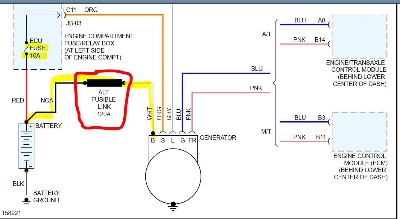
Check for full battery voltage on the large output wire when the engine is off. For this type of problem, a cheap test light, (one with an incandescent bulb inside), can be more accurate than a digital voltmeter.

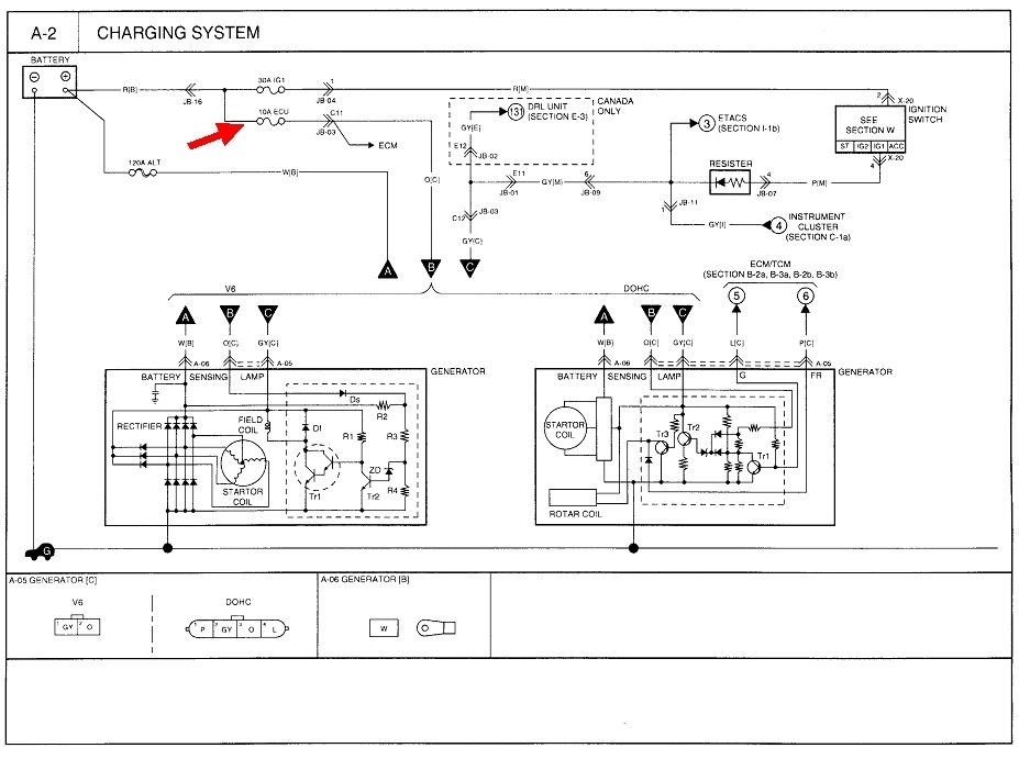
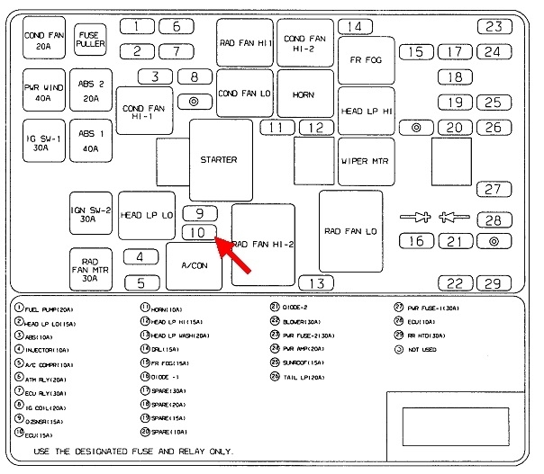
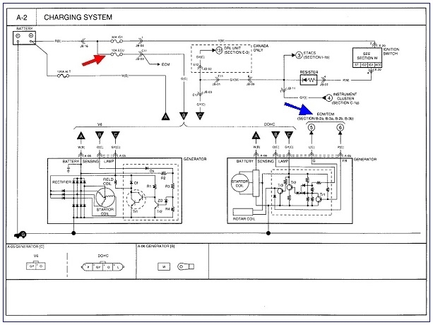
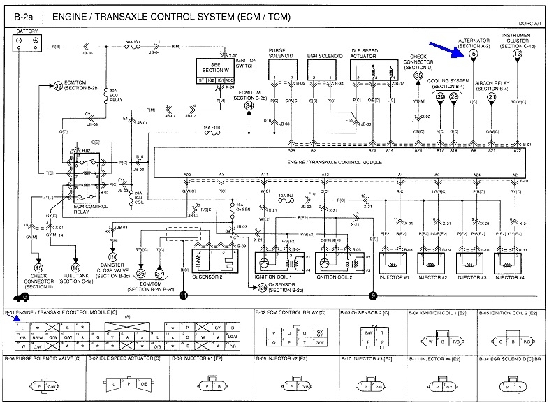
Next, there should be full battery voltage at all times on point "B", which looks to be an orange wire. If that is missing, suspect the 10-amp "ECU" fuse. That's the one with my nifty red arrow, but it feeds the Engine Computer too, so you should be diagnosing a crank / no-start issue if that fuse was blown. This is the fuse that is commonly blown and commonly overlooked on Ford products.

While it isn't obvious, it looks like the field winding gets energized on the gray wire, point "C", when the ignition switch is turned on. The resistor they show between the ignition switch and point "C" does not appear to be the one used when the dash light burns out. In fact, I'm not sure what it is for, but that is a good suspect if you're missing the 12 volts on that gray wire. This does not appear to be a "turn-on" circuit as they do it on Fords. We're lucky in that they show a representation of what is inside the voltage regulator.

Let me start by describing how the Ford system works because that might shed light on this system in a minute. With Fords, their yellow wire, (the orange one on this Kia system), has 12 volts all the time, and that is the feed for the field winding. The other end of that winding gets grounded and controlled by the voltage regulator, and the regulator turns on to do its thing when it gets current flow on the green / red wire from the dash warning light. Since the light bulb drops most of the 12 volts, you're left with around 2.0 volts on that wire at the generator, (gray wire here). That 2.0 volts is enough to tell the regulator to turn on and start conducting some current through the field winding. Now you have a magnetic field and the stationary stator winding. All that's left is the most important thing, that is movement between them. Once the engine is running, the movement causes voltage to be induced in the stator, and that produces the output current. System voltage continues to be monitored on the yellow wire, then the regulator adjusts how much current flows through the field winding, to control output current and voltage.

Once the system is developing an output, a sample of that is tapped off and goes right back into the voltage regulator to tell it the system is working. (That's the short white / black wire on the Ford generator). In response, the regulator sends full charging voltage back out on the green / red dash light wire. With that full system voltage on one side of the warning bulb, and the same full system voltage on the other side of the bulb, from the ignition switch, the difference is 0 volts, so the bulb goes off.

Here, in your Kia system, operation isn't so easy to follow. System voltage is still monitored on the orange wire, but that is not the current supply for the field winding, at least not as the representation is drawn. Since this is a constant feed to the internal circuitry, there has to be some other way to stop current flow when the engine is off, to prevent draining the battery overnight. It looks like that is all done with the gray wire from the ignition switch. That feeds the field coil directly, then current flow continues through a regulating transistor, then to ground. Of interest is right above the field coil, the circuit taps off to the right and feeds the rest of the circuitry. This is where it differs from the Ford system, and while it is a simpler design, it is not obvious what turns the dash light on and off.

If you look again at that resistor, the circuit goes to the instrument cluster at point "4". Stop there for a minute, and look at the three diodes on the left side of the left alternator diagram, right under the word, "rectifier". That is the same "diode trio" used for many years in GM generators, up to 1986. Once the system is up and running, a small sample of current goes through those three diodes and continues to supply the current for the field winding, and it goes back to the dash light to turn it off. It looks like that's what they're doing here too.

My suspicion is when you turn on the ignition switch, current flows through the "dropping" resistor, then what voltage remains is applied to the field winding. That may be only 2 volts, but that would be enough to get the process started. I also suspect there's 12 volts applied to the other side of the dash light, so with 12 volts on one side and 2 volts on the other, the light turns on.

Next, when the engine is running, the current developed through the diode trio brings the voltage feeding the field coil up to full charging voltage, and keeps going higher and higher until the regulator kicks in to limit any further voltage increase, and at the same time, that full voltage goes back to the dash light to turn it off.

So, ... Now that I've shared all that wondrous information, it looks like the gray wire is where we're going to find the problem. You may need to resort to using a digital voltmeter to see what you have when you back-probe that wire. Expect to see a low voltage there before you start the engine, and the dash light should be on. If those two things are missing, suspect a break in that wire, the resistor is burned open, or the connector terminal is spread and not making contact with its mating terminal at the generator.

Even when that gray wire has a problem, that circuit is only there to insure the system starts up. There is often enough residual magnetism in the field winding, (rotor), to get the system started, then it will "self-excite" through the diode trio and get up to full output instantly. Since the third important ingredient in generating a voltage this way is the movement between the stator and the magnetic field, you often have to raise engine speed to get the system to self-start. Once it is started, as with the Ford systems, you can take the gray wire away and the generator will keep right on humming along as long as the rotor keeps on spinning. Once the engine is stopped, you'll have to go through that again and hope it self-starts again. This used to be common on hot rods that used a GM generator with only a single output wire going back to the battery. There were no other wires connected to it. They relied on that residual magnetism to eventually get it going once the engine reached a high enough speed.
Was this
answer
helpful?
Yes
No
Friday, January 10th, 2020 AT 6:39 PM
Tiny
JACOBANDNICKOLAS
  • MECHANIC
  • 108,133 POSTS
Hi,

If the alternator light on the dash is bad, it won't prevent the alternator from charging the battery. It will prevent you from knowing of the alt isn't charging at all.

What I need you to do is check two things. First, there is a fusible link between the battery and the alternator (white wire on alt). I need to confirm there is 12v power to it all the time.

Next, check the 10 amp fuse I circled in the pic.

A fusible link is a wire that functions as a fuse. If bad, it will melt down internally to open the wire and prevent power flow. If there is no power to the alt, it won't charge.

Also, if possible, check alternator output. Here is a link that is easy to follow and explains how to check:

https://www.2carpros.com/articles/how-to-check-a-car-alternator

Let me now what you find.
Joe
Was this
answer
helpful?
Yes
No
+1
Friday, January 10th, 2020 AT 6:41 PM
Tiny
THOMAS SHATAS
  • MEMBER
  • 6 POSTS
Turns out that a lot of Kia Optima alternator problems are caused by road salt splashing onto exposed plugs and wires on the back of the alternator and causing the copper wires to become corroded, brittle and break due to crappy engineering. Pretty much everything that fails on a Hyundai or Kia is due to substandard engineering of some sort or another.
Was this
answer
helpful?
Yes
No
Sunday, January 12th, 2020 AT 12:20 PM
Tiny
CARADIODOC
  • MECHANIC
  • 33,727 POSTS
Does that mean you solved the problem?
Was this
answer
helpful?
Yes
No
Sunday, January 12th, 2020 AT 2:38 PM
Tiny
THOMAS SHATAS
  • MEMBER
  • 6 POSTS
I am still waiting for new alternator plug before I confirm my diagnosis.
Was this
answer
helpful?
Yes
No
Monday, January 13th, 2020 AT 9:07 AM
Tiny
JACOBANDNICKOLAS
  • MECHANIC
  • 108,133 POSTS
Let us know what you find out. This is an interesting one.

Take care,
Joe
Was this
answer
helpful?
Yes
No
Monday, January 13th, 2020 AT 7:25 PM
Tiny
THOMAS SHATAS
  • MEMBER
  • 6 POSTS
Thanks for all your help but still no luck figuring out the problem. I have accomplished replacing the resistor diode package with a new one, confirmed that the connector to the alternator was functioning as intended, alternator has been tested on four testers, disconnected ETACS from circuit to test if it might have failed and drew power from the circuit, only item not tested was the ECU and its connection because I have not found a replacement unit. I observe a brief moment of charging on my meter when the car first starts and the charge light briefly goes out but returns to charge light on and the electronic meter shows a brief spike to above 13 volts but then returns to a discharge voltage again. If I remove the connection to the possibly bad ECU, will this harm the circuitry any worse than it is. It seems like a test worth making since the previous owner gave up figuring this problem out and installed a deep cycle battery and simply recharged the battery when he could and did not drive the vehicle at night if he could avoid it. I surmise this is why the vehicle has only 80,000 miles on it.
Was this
answer
helpful?
Yes
No
Tuesday, January 28th, 2020 AT 1:19 PM
Tiny
THOMAS SHATAS
  • MEMBER
  • 6 POSTS
Also could you inspect the circuit diagram and suggest a circuit wiring diagram that could convert this alternator into a one wire alternator like what GM used to make?
Was this
answer
helpful?
Yes
No
Tuesday, January 28th, 2020 AT 1:23 PM
Tiny
CARADIODOC
  • MECHANIC
  • 33,727 POSTS
To generate a current mechanically, as with a generator, you need three things. You need a wire, (coil of wire is more efficient), a magnet, (we use an electromagnet because it is real easy to adjust its strength), and most importantly, movement between them. That movement is why we spin the electromagnet with a belt and pulley.

In those GM one-wire generators, they relied on the little residual magnetism in the iron core of the rotor, or "field" winding, to get things started. Since that magnetic field was so weak, a lot more speed of movement was needed to get things started. Once that occurred, some of the current that was developed was tapped off to go right back through the field winding to build a stronger magnetic field. That process would continue until the engine was stopped. That current to run the field winding came through a set of three diodes put there specifically for this purpose. That was the "diode trio". It also supplied the current to run the internal voltage regulator.

To modify the system and run the generator directly, the most popular and easy to use regulator is Chrysler's electronic voltage regulator they used from 1970 through a few models in 1989. I'm even using one right now to run the generator on my skid steer, but I had to modify it to remove its internal regulator.

The problem with doing this with your generator is that internal voltage regulator. With the four-cylinder engine, the diagram on the right is used, and it shows two circuits going to the Engine Computer. The diagram for the regulator is only a representation, not the actual circuitry, so it's impossible to know if that can be incorporated into a custom circuit. This is what I ran into with my skid steer and is why I had to go inside and attach wires there.

With the system on the four-cylinder engine, charging voltage is further modified by a signal from the Engine Computer. That is done because that computer knows more stuff than does the voltage regulator. For example, the computer knows when wide-open-throttle is reached, or the engine is under heavy load. It knows when a higher electrical load is about to be switched on, like the rear defroster or AC compressor, and it can bump up charging voltage in anticipation of those events. If the engine is getting too hot, the computer can reduce generator output to reduce load on the engine.

In this case there is no description in the service data to explain what that circuitry is doing or how to diagnose if that is what is causing the problem.

From the observations you just added, it sounds like the rest of the circuitry is working, but the Engine Computer is either kicking in to cut back on charging voltage, or it is not telling the regulator to go ahead and bring system voltage up to specs. From my many years in tv repair, the way you described charging voltage looking okay for a few seconds, then gradually dropping off, is reminiscent of a failing transistor that is affected by the heat generated inside it. In this case that suspect would be in the Engine Computer. We can rule out the generator and voltage regulator because you've had it tested and the symptoms were the same with multiple units.

Due to the lack of information, there's three things I see here. One is the generator and voltage regulator which have been verified as working. The second is the Engine Computer which we suspect, but don't know how to test. Typically we rule out everything else until we're left with the one suspect. The third is the wiring, which we can look at.

The second and third diagrams show the parts of the Engine Computer where the two charging system wires go to. Those terminals should be checked for corrosion, and the wires for continuity.

The way I would approach the Engine Computer is the same way we diagnosed defective integrated circuits in tvs and vcrs. You need all the power supplies, and all the grounds, then, assuming nothing is shorted on the output circuits, if you have the proper input signals, you should get the proper output signals. In the majority of those cases, it was an input voltage that was missing, or it was a defective IC.

Every computer is going to have multiple supply voltage terminals and multiple grounds. Almost all the time a ground is missing, there are going to be multiple other problems besides just a failure to charge, so grounds are down low on the suspect list. One of the 12-volt feeds to the Engine Computer, besides being used to run other circuits, is also the point at which the computer senses system voltage. We don't always know which one that is, so we have to look at all of them.

The third and fourth diagrams show the 12-volt feeds that I found. Those are the terminals to pay special attention to. As this circuit is drawn, all of them have 12 volts all the time. Some place either something has to be switched on and off through the ignition switch, or, as is commonly done today, it is only the Body Computer that is switched on through the ignition switch, then it sends digital signals out on the "data buss" wires to tell all the other computers to turn on. I can't find any switched 12-volt circuits, so check those I have pointed out, and expect them to be there with the ignition switch on or off.
Was this
answer
helpful?
Yes
No
Tuesday, January 28th, 2020 AT 3:24 PM

Please login or register to post a reply.

Sponsored links