Need exact throttle body actuator wiring harness

Tiny
CHRISTA DICKSON
  • MEMBER
  • 1998 LEXUS GS 300
  • 250,000 MILES
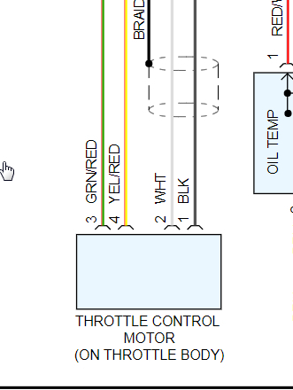
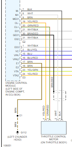
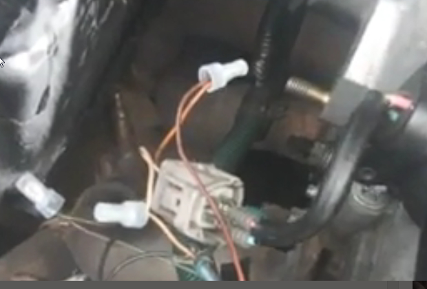
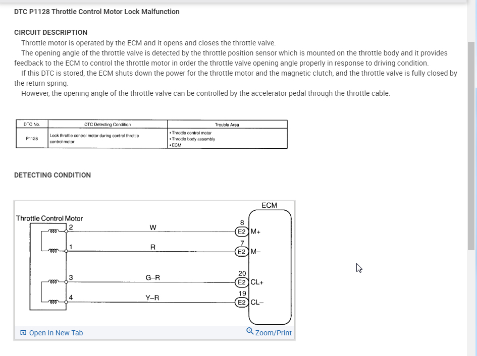
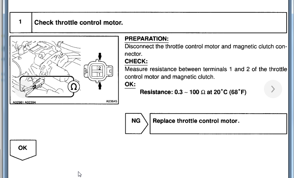
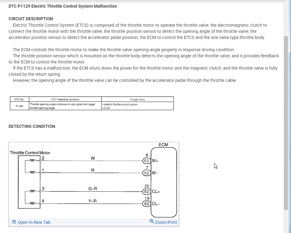
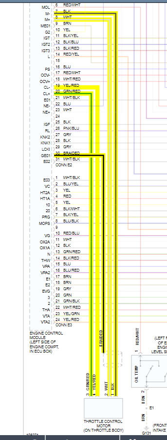
One of the wires pulled out of the electrical connection as a for that plug the throttle body actuator on to the throttle body assembly itself. There are four wires in each and I have thought about just twisting them together but one side of the wires is way sicker than the other. Would that be okay to go ahead and do need color coded wiring diagram? Please ASAP.
Do you
have the same problem?
Yes
No
Friday, April 17th, 2020 AT 1:18 PM

10 Replies

Tiny
KASEKENNY
  • MECHANIC
  • 18,907 POSTS
Here is a picture of the wiring diagram for the throttle body. Let me know if you need more detail but if you have a wire that pulled out of the connector you can just use a connector kit and solder the wires back together. If I understand the issue correctly then the better route is to get a new connector with the wiring on it and then just solder it onto the existing wiring. Let me know if I am misunderstanding the issue or if you have questions. Thanks
Was this
answer
helpful?
Yes
No
-1
Monday, April 20th, 2020 AT 4:03 PM
Tiny
DANNY L
  • MECHANIC
  • 5,648 POSTS
Hello, I'm Danny.

Here is a color wiring diagram you requested. The 4 wires originate from the ECM (engine control module) I've attached the picture below. Hope this helps and thanks for using 2CarPros.
Was this
answer
helpful?
Yes
No
-1
Monday, April 20th, 2020 AT 4:04 PM
Tiny
CHRISTA DICKSON
  • MEMBER
  • 138 POSTS
Thanks for your reply, but I am unclear on the braided wire I have ran into it while having to fix this and the crank plug by alternator harnesses and not really sure what to do with the wire? Should I cut it off, ground it to something or where does it go?
Was this
answer
helpful?
Yes
No
Saturday, April 25th, 2020 AT 1:28 PM
Tiny
KASEKENNY
  • MECHANIC
  • 18,907 POSTS
Can you get pictures of what you are dealing with? If you have a connector issue at the throttle body then that is all we need to fix. As for the twisted pair wiring, we just need to connect the new wiring from a connector kit. Just get us pictures of the wiring and connectors that you are trying to repair and we can get you the info that you need to repair it. Thanks
Was this
answer
helpful?
Yes
No
Sunday, April 26th, 2020 AT 6:01 PM
Tiny
CHRISTA DICKSON
  • MEMBER
  • 138 POSTS
I also have a piece of the thicker wired side coming from the motor itself cut off from pick n pull that is not broken. If you think it would be better to spice and reconnect the harness that way, but would this be causing no start and how can I fix it? Please keep in mind no ride if possible.
Was this
answer
helpful?
Yes
No
Monday, April 27th, 2020 AT 12:16 PM
Tiny
KASEKENNY
  • MECHANIC
  • 18,907 POSTS
Okay. That video helped but it actually was cut off at the bottom so we couldn't actually see the wiring when you were showing it. So can you get pictures of the two areas that you made those wiring repairs? It seems like you have tried to bypass these sensors? Is that true? Is the connector that is shown below the throttle motor connector?

If you are trying to bypass these components that is the reason for the no start. You can't bypass them. If the ECM doesn't get a signal from these sensors then it will cause what you are dealing with.

The codes you gave me were circuits codes for these circuits and are the cause of your no start. We need to put the wiring back to factory so that we can repair the vehicle for what the issue was before you tried to bypass these things.

Let me know if that is what is happening here and if not, can you get pictures and then show me why you are twisting wires together. Thanks
Was this
answer
helpful?
Yes
No
Tuesday, April 28th, 2020 AT 2:19 PM
Tiny
CHRISTA DICKSON
  • MEMBER
  • 138 POSTS
No didn't try to bypass anything just fuse connector. Still wont start. Code 1128, 1129 and 1130 and pretty sure I have wiring right would appreciate verification.
Was this
answer
helpful?
Yes
No
Wednesday, April 29th, 2020 AT 5:57 AM
Tiny
KASEKENNY
  • MECHANIC
  • 18,907 POSTS
Okay. So if you are just jumping past a connector then that is okay. However, those connectors are not going to hold up. They are okay for now but each of those connections will need to be soldered and heat shrink wrapped.

I attached the testing for these codes. We need to run through this and see what we come up with. I agree that I suspect a wiring issue but the codes are telling us where to start so let me know if you have questions or the results and we can go from there. Thanks
Was this
answer
helpful?
Yes
No
Wednesday, April 29th, 2020 AT 7:04 PM
Tiny
CHRISTA DICKSON
  • MEMBER
  • 138 POSTS
It's reading 1.8 steady resistance and i'm pretty sure there's nothing in it because I have already switched it out, but will check again. What should I do next? It's starting then sputtering out like with a second or two every time.
Was this
answer
helpful?
Yes
No
Thursday, April 30th, 2020 AT 6:04 AM
Tiny
KASEKENNY
  • MECHANIC
  • 18,907 POSTS
Okay. Based on these results then the ECM is the issue. However, I would suggest ohm out the wiring from the ECM to the throttle motor. This means unhook each connector and test resistance from end to end. You should have around a half ohm or less on each wire. If you have good continuity and proper resistance then I suspect the ECM is the issue due to these codes.
Was this
answer
helpful?
Yes
No
Friday, May 1st, 2020 AT 9:13 AM

Please login or register to post a reply.

Sponsored links